the Creative Commons Attribution 4.0 License.
the Creative Commons Attribution 4.0 License.
 | 09 Jun 2021
Whistler waves produced by monochromatic currents in the low nighttime ionosphere
Vera G. Mizonova
Peter A. Bespalov
We use a full-wave approach to find the field of monochromatic whistler waves, which are excited and propagating in the low nighttime ionosphere. The source current is located in the horizontal plane and can have arbitrary finite distribution over horizontal coordinates. The ground-based horizontal magnetic field and electric field at 125 km are calculated. The character of wave polarization on the ground surface is investigated. The proportion in which source energy supplies the Earth–ionosphere waveguide or flows upward can be adjusted by distribution of the source current. Received results are important for the analysis of ELF/VLF emission phenomena observed both on the satellites and on the ground.
- Article
(2125 KB) - Full-text XML
- BibTeX
- EndNote


ELF/VLF waves, which propagate in the ionosphere in whistler mode, are an important part of the ionosphere dynamics. Such waves can be emitted by various natural phenomena such as atmospheric lightning discharges and volcanic eruptions, magnetospheric chorus and hiss. Artificial ELF/VLF waves have been produced by ground-based transmitters and by modulated high-frequency (HF) heating of the ionosphere current system responsible for Sq variations or the auroral electrojet, which is by now a well-known technique. ELF/VLF waves modulated by the HAARP heating facility can be injected in the Earth–ionosphere waveguide as far as 4400 km (Moore et al., 2007) and also into space (Inan et al., 2004).
Several numerical methods have been developed for calculating whistler wave fields in the Earth's ionosphere (Pitteway, 1965; Wait, 1970; Bossy, 1979; Nygre'n, 1982; Budden, 1985; Nagano et al., 1994; Yagitani et al., 1994; Shalashov and Gospodchikov, 2011). One of the main difficulties is numerical instabilities caused by a large imaginary part of the vertical wave number. General full-wave analysis, including the problem of numerical “swamping” of the evanescent wave solutions, was performed, for example, by Nygre'n (1982), Nagano et al. (1994), and Budden (1985). A traditional approach in full-wave analysis is to divide a stratified ionosphere into a number of thin horizontal and homogeneous slabs and then connect the solutions in each slab by applying the boundary conditions. Such a technique has been used by Yagitani et al. (1994) to study ELF/VLF propagation from an infinitesimal dipole source located in the lower ionosphere. The idea of recursive calculation of mode amplitudes was developed and used for an arbitrary configuration of the radiating sources by Lehtinen and Inan (2008). Nevertheless, finding fields created by both natural and artificial ELF/VLF radiating sources is still very relevant.
In this paper, we use numerical methods to find the field of ELF/VLF waves, which have been produced in a low nighttime ionosphere. On the one hand, significant inhomogeneity of plasma parameters, strong wave mode attenuation and effect of wave mode transformation (for example, whistler to vacuum electromagnetic) in the low-altitude nighttime ionosphere make the problem considered difficult enough and fundamentally important. On the other hand, it has practical significance, as an example, for interpretation of numerous experimental results on HF heating which modulate natural ionospheric currents at altitudes of 60–100 km.
In calculations, we use a technique known as the two-point boundary-value problem for ordinary differential equations (Kierzenka and Shampine, 2001). Using this technique in early work (Bespalov and Mizonova, 2017; Bespalov et al., 2018) has provided numerically stable solutions of a complete system of wave equations for arbitrary altitude profiles of plasma parameters and in the stratified ionosphere for arbitrary angles of wave incidence from above. Here, we find a wave field created by a monochromatic source current located in the low night ionosphere. We examine the influence of peculiarities of current distribution on the proportion in which source energy supplies the Earth–ionosphere waveguide or flows upward. As an example of calculations, we use current distributions similar to those simulated by HF heating of the auroral electrojet (Payne et al., 2007). The obtained results are important for analysis of the ELF/VLF emission phenomena observed both in the ground-based observatories and onboard satellites.
We consider a whistler wave which is excited and propagating in the layer of the non-homogeneous stratified ionosphere. We choose a coordinate system with a vertical upward z axis and x and y axes in the horizontal plane, suppose that plasma parameters depend on coordinate z, plane z=0 corresponds to the ground surface, above the boundary ionosphere plasma is close to homogeneous, and the ambient magnetic field B0 belongs to the y–z plane and is inclined at an angle ϑ to the z axis. We assume that external currents have monochromatic dependence on time and flow in the source plane z=zs:
At first, we use the Fourier composition of the source current density over the horizontal coordinates,
and wave electric and magnetic fields at each altitude
and find field amplitudes , corresponding to the horizontal wave vector component , . Here we use SI units for E and modified units for H=Z0HSI (Budden, 1985), where is the impedance of free space. Then we write the Maxwell equations
where c is the speed of light in free space and is the permittivity tensor, which yield a set of four equations for the horizontal components , (in a case of a source-free medium, see, e.g., Budden, 1985, Bespalov et al., 2018, and Mizonova, 2019)
Here we have taken into account that the horizontal refractive index of the wave propagating through the stratified medium is conserved due to Snell's law. In Eq. (5) and are four-component column vectors
is a matrix of which the elements mij are expressed in terms of components of the transverse wave vector , and ε, η, and g are elements of the permittivity tensor which depends on the z coordinate (Bespalov and Mizonova, 2017; Bespalov et al., 2018), .
To solve the system in Eq. (5), in Eq. (6) we define four boundary conditions. We write two of them on the plane z=0 assuming the ground surface to be perfectly conductive:
We write two other conditions on the plane excluding wave energy coming from above. To clarify them, we express the field vector column F above the boundary as the sum of four wave modes
Here Aj=const, kzj are four roots of the local dispersion relation and Pj are four corresponding local polarization vectors. We mention that values kzj and vectors Pj are the solutions of Eqs. (5) and (8) for homogeneous plasma without sources. Assuming that indices 2 and 4 correspond to coming from above-propagating and non-propagating wave modes (imaginary parts of kz2 and kz4 are negative), we write
Solving the set of Eq. (5) with known source current density Eq. (6) and boundary conditions Eqs. (7) and (9), we can find the field of the plane wave with horizontal wave vector in the layer . Then, we use the inverse transform
to calculate the total field.
We take into account that out of the plane z=zs, the source current density Eq. (6) is equal to zero, so Eq. (5) becomes
To solve Eq. (11) in layers and , we apply packaged solver MATLAB bvp4c and use a method known as the two-point boundary-value problem for ordinary differential equations (Kierzenka and Shampine, 2001). The solver solution starts with an initial guess supplied at an initial mesh point and changes step size to get the specified accuracy.
At first we find two linearly independent solutions F1 and F2 of Eq. (11) in the layer completing the boundary condition Eq. (7) on the plane z=0 for arbitrary conditions on the plane . For example, we use four conditions , , , and for the solution F1 and four conditions , , , and for the solution F2, where E is constant. Then we write the general solution in the layer as the sum
Similarly, we find two linearly independent solutions and of Eq. (11) in the upper layer completing the boundary condition Eq. (9) on the plane . By arbitrary conditions on the plane , we have A2=0, A4=0, , and and A2=0, A4=0, , and , respectively. We write the general solution in the layer as the sum
Integrating Eq. (5) over the z coordinate in a narrow layer , we find a condition connecting solutions Eqs. (12) and (13):
That condition yields four algebraic equations for the coefficients a, a*, b, and b*. Thus, finding those coefficients, we obtain the wave field F Eq. (6) in the layer . In particular, the fields on the ground surface can be expressed as
where , are electric strength components of the incident wave in the coordinate system with the z′ axis along the ambient magnetic field. The wave polarization near the ground surface is determined by
The electric field at the altitude can be expressed as
The coordinate dependence of the wave field can be found from the inverse Fourier transform Eq. (10). The vertical energy flux (Poynting vector) is
and the total power of the source is
Now we present the results of the numerically computed solution of the set Eqs. (5) and (6) under model conditions for the nighttime ionosphere.
In the calculations, we use the altitude profiles of the plasma density shown in Fig. 1a and the collision frequencies between charged and neutral particles shown in Fig. 1b. The plasma density data are taken from International Reference Ionosphere (Bilitza and Reinisch, 2007), available from CCMC at https://ccmc.gsfc.nasa.gov/modelweb/models/iri2016_vitmo.php (last access: 28 April 2021), and correspond to 680 N, 250 E; 4 September 2019, 00:30 LT. The collision frequency data are taken from the book of Gurevich and Shvarcburg (1973). The angle of magnetic field inclination with respect to the axis z is equal to ϑ=1680. We use the value as the upper boundary of the solution. At this altitude a typical spatial scale of plasma inhomogeneity exceeds 70 km, and it is much more than the wavelength, which in the considered case is on order 20 to 25 km. As an example, we calculate the fields created by varying at frequency 3 kHz and flowing at the altitude zs=80 km horizontal current.
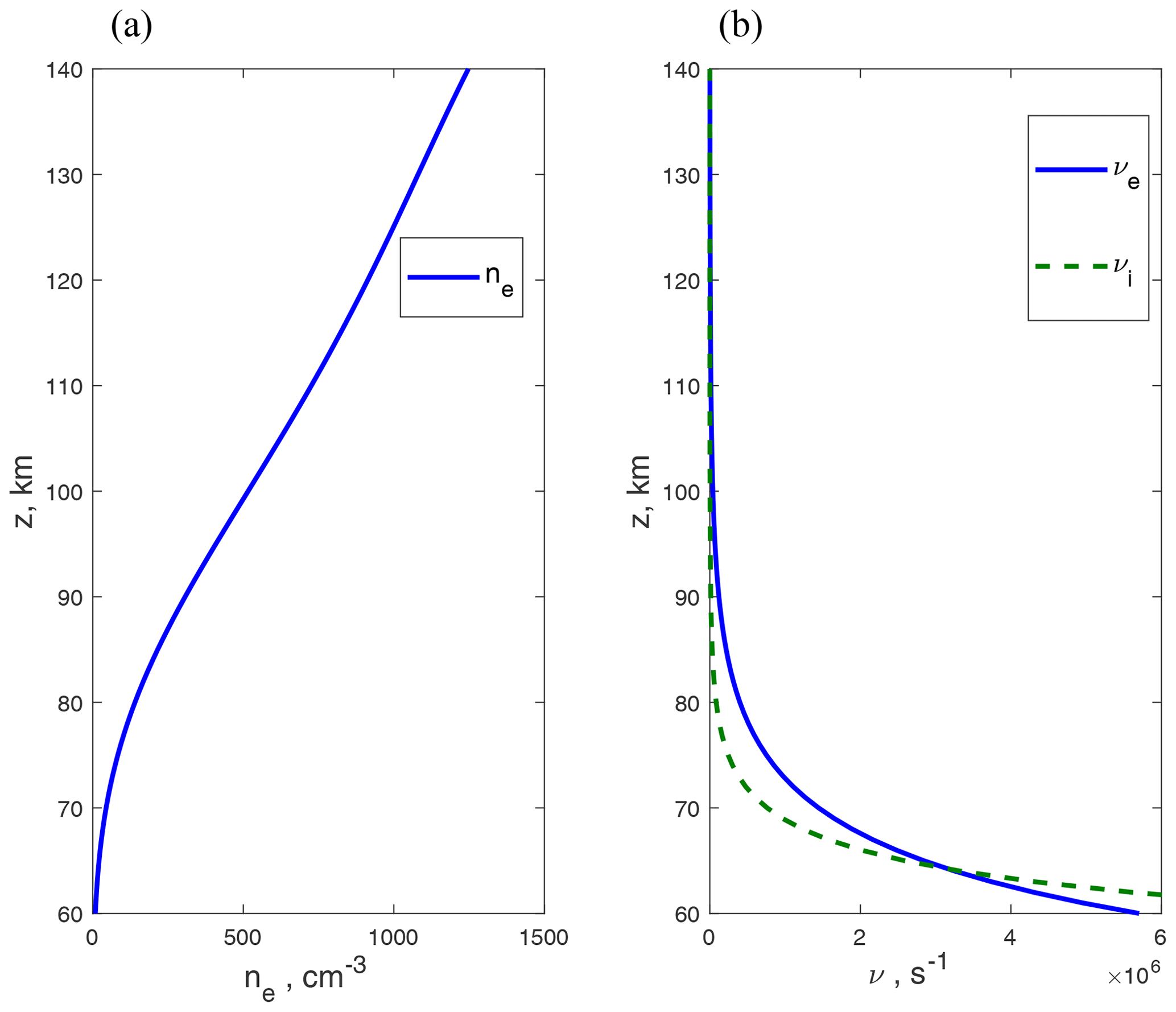
Figure 1Nighttime ionosphere model: (a) the electron plasma density and (b) the collision frequency between electron and neutral particles (solid line) and collision frequency between ion and neutral particles (dashed line).
We assume that currents occupy a volume which has a shape of a horizontal pancake and use for calculations a Gaussian distribution over x and y coordinates
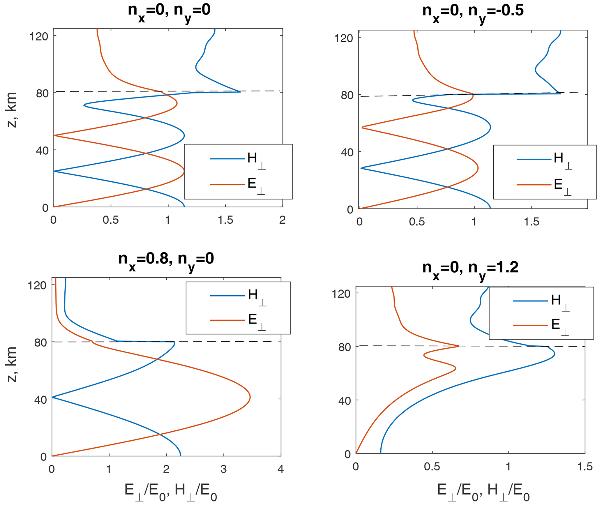
The corresponding current distribution Eq. (2) in Fourier space is also Gaussian and has a form J(n⊥) = , where . We calculate the wave field in N=1000 points with steps and then use inverse fast Fourier transform (Cooley and Tukey, 1965) to find its coordinate dependence. We present the results of field calculation in Fourier space (Figs. 2–3) and in coordinate space (Fig. 4). The dependences of amplitude of horizontal magnetic field on ground surface z=0 and amplitude of electric field at altitude are presented in Fig. 2a, b. The field values are normalized by the value E0=Z0J0. Polarization ellipse parameters ϕ, , and are presented in Fig. 2c, d. Positive values of phase ϕ correspond to right-hand polarization, typical for whistler waves, and negative values of phase ϕ correspond to left-hand polarization. Positive values of parameter mean that the polarization ellipse is elongated predominantly along the y axis, and negative values of parameter mean that the polarization ellipse is elongated predominantly along the x axis. Examples of altitude dependences of normalized electric and magnetic fields corresponding to different horizontal refractive indices are presented in Fig. 3. The level z=zs of the source action is marked by a dotted line. Figure 4 shows contour maps of fields created by horizontal currents (20) with characteristic horizontal sizes Lx≃12 km, Ly≃70 km and equal x and y components Jx=Jy current density (Fig. 4a), electric field at altitude (Fig. 4b), horizontal magnetic field on ground surface z=0 (Fig. 4c) and polarization parameter ϕ (Fig. 4d). Current density is normalized by the value Jmax, both electric and magnetic fields are normalized by the value Z0Jmax, and the arrow shows the current direction. Examples of ground-based horizontal magnetic field and electric field at altitude corresponding to the coordinate x=0, characteristic horizontal sizes of source Ly≃70 km, Ly≃12 km and different distributions of Jx,y are presented in Fig. 5.
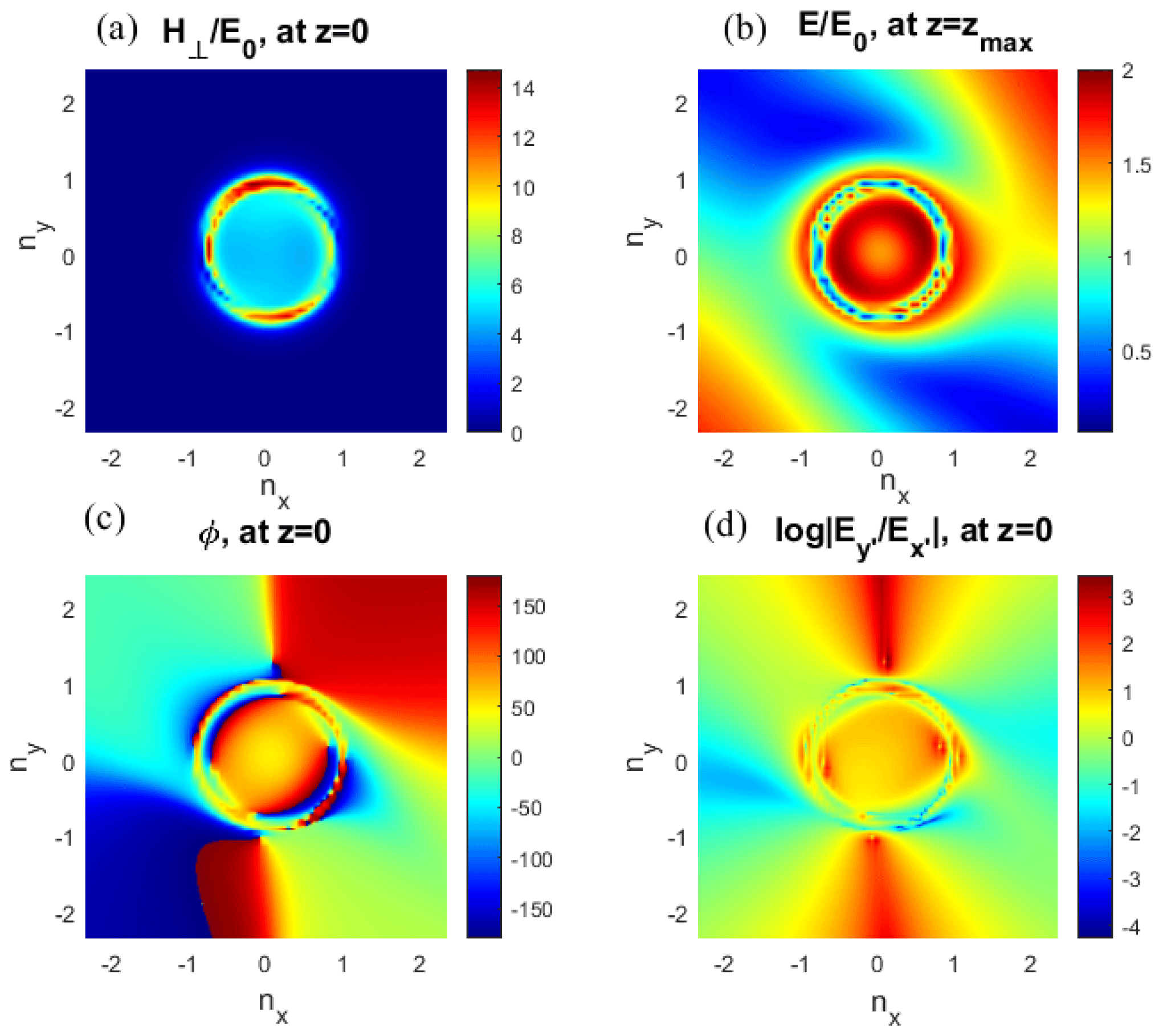
Figure 2Fields in the z=0 plane: (a) characteristic horizontal sizes of the horizontal magnetic field, (b) the electric field at the height z=125 km, (c) the polarization ellipse parameters , and (d) .
We use a full-wave approach to find the field of monochromatic whistler waves which are excited and propagating at night in the strongly inhomogeneous low ionosphere. A source current is assumed to be located in the horizontal plane and to have in this plane an arbitrary finite-space distribution. At first, we consider a plane wave with the horizontal components of the refractive index n⊥ generated by the current . The set of wave equations in the layer for each n⊥ component is completed by boundary conditions assuming a perfect conductivity of the ground surface and excluding wave energy coming on the upper boundary from above. The mathematical method known as the two-point boundary-value problem for ordinary differential equations (Kierzenka and Shampine, 2001) is applied to find the solutions of wave equations above and below the source plane. Then we connect these solutions using source current distribution. When the dependencies of source current and wave field in n⟂ space are finite functions with discretized values, the fast Fourier transform algorithm can be used for numerical calculations. Inverse fast Fourier transform yields space dependence of the wave field.
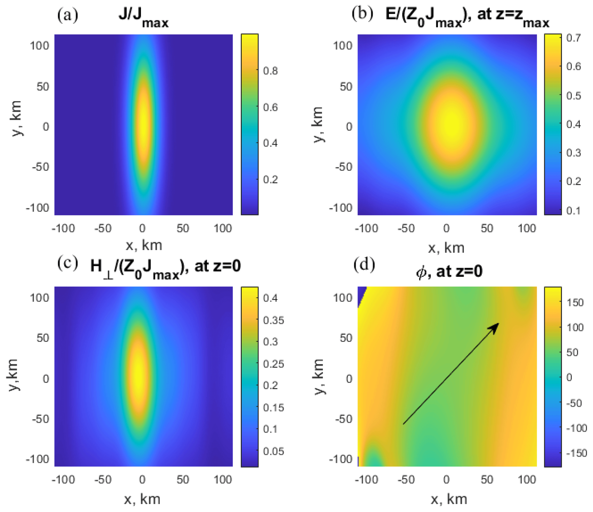
Figure 4Source currents and field space distributions: (a) space distributions of source currents, (b) the electric field at z=125 km, (c) the horizontal magnetic field at z=0, and (d) the polarization ellipse parameters ϕ, at z=0.
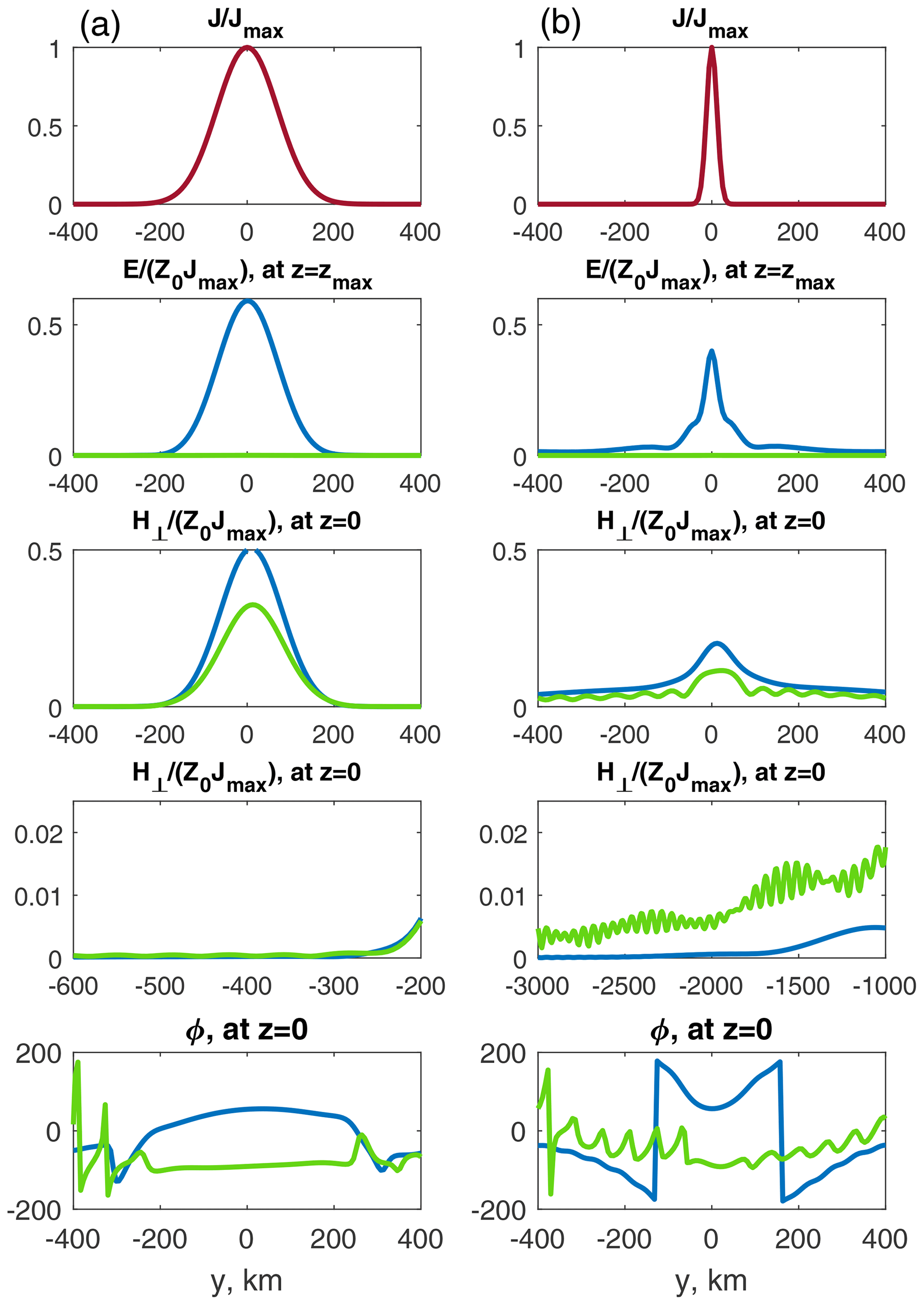
Figure 5Current density (red line) and field space distributions at x=0 for two different ratios , outlined by green () and blue () colors. Left plot column (a) corresponds to the source scale and right plot column (b) corresponds to the source scale.
As an example, we calculate the fields created by varying at a frequency of 3 kHz and flowing at zs=80 km horizontal current, with a Gaussian distribution of source current density over x and y coordinates. We mention that the model of a plane source current can also be effective in a more general case of a current layer with small thickness . The ground-based horizontal magnetic field and the electric field at 125 km are calculated in both Fourier (nx, ny) and coordinate (x, y) spaces, since a wave can achieve the ground surface in penetrating mode in case . The magnetic field is noticeably non-zero for Fourier components with and is practically equal to zero for Fourier components with . Waves with are right-hand-polarized (see Fig. 2c), which is typical for whistlers. However, if the horizontal component of the refractive index has an order of unit, then the magnetic field can increase by 2 or 3 times (see Fig. 2a). The polarization parameter ϕ of such components can be negative, similarly to the left-hand-polarized waves (see Fig. 2c). A typical size of the spot and a character of polarization of the ground-based magnetic field depend on the source distribution. If the horizontal size of the radiating currents exceeds a value (for the wave of frequency 3 kHz), then the Fourier components with dominate in the total field. In that case, the magnetic field is predominantly localized under the source. If the horizontal size of radiating currents is small enough , then Fourier components can make a notable contribution to the total field. The magnetic field occupies a spot but can sometimes be registered far from the source (see Figs. 4c, 5b). The field above the source is determined by both direct radiation from the source and the reflected radiation. Because of the effective night reflection of ELF/VLF waves, a spot of the electric field at 125 km can exceed the size of the source by several times (Fig. 4b).
At altitudes of source and above, the two ELF/VLF wave modes Eq. (8) are weakly damped and have right-hand polarization, and another two modes are evanescent and have left-hand polarization. At altitudes ∼60–70 km and below all four modes transform into vacuum electromagnetic ones. Source currents can excite both right-hand- and left-hand-polarized modes. Hence, current distribution properties specify field distribution, field polarization, and proportion in which source energy supplies the Earth–ionosphere waveguide or flows upward. As an example, Figs. 5a, b show coordinate dependencies of source density, fields , and polarization parameter ϕ in cases of large (a) and small (b) sources for two different ratios in distribution (20), outlined by green and blue colors. In the first case of ratio (blue lines on the plots), source currents excite predominantly right-hand-polarized modes. So the polarization parameter at z=0 is mainly positive under the source. Approximately 50 %–60 % of the source energy is carried upward, 30 %–40 % is adsorbed, and about 10 % is supplied to the Earth–ionosphere waveguide. This can be useful for modification processes in the plasma magnetic trap (Bespalov and Trakhtengerts, 1986). Of course, the electromagnetic ELF/VLF radiation of ionospheric currents themselves is not sufficient for a noticeable modification of the Earth's electron radiation belts. However, under quiet conditions in the nighttime magnetosphere, these emissions can ensure the radiation belt transition through the threshold of the cyclotron instability. This process can be accompanied by a significant precipitation of energetic electrons into the ionosphere and other geophysical manifestations.
In the second case of ratio ratio (green lines on the plots), source currents excite predominantly left-hand-polarized modes. Respectively, the polarization parameter at z=0 becomes predominantly negative. In that case, regardless of source size, approximately 10 %–12 % of the energy is supplied to the Earth–ionosphere waveguide, and about 90 % is absorbed and not carrying upward to the magnetosphere. The proportion in which source energy supplies the Earth–ionosphere waveguide or flows upward mainly depends on polarization of the source current.
If the horizontal size of radiating currents is small enough, , a ground-based magnetic field can be noticeably non-zero far (a few thousand kilometers) from the source (see Fig. 5b). Propagation of modulated ELF/VLF signals in the Earth–ionosphere waveguide far from the source and also into space (Inan et al., 2004) is observed experimentally. The HAARP heating facility in Gakona, Alaska, injects ELF/VLF waves in the Earth–ionosphere waveguide as far as 4400 km (Moore et al., 2007).
The current distributions used as an example in our calculation and presented in Fig. 4 can be similar to electrojet currents modulated in the D region by the HAARP HF heating facility (Keskinen and Rowland, 2006; Payne et al., 2007). For example, according to data collected during an experimental campaign run in April 2003 and results of numerical simulations (Payne et al., 2007; Lehtinen and Inan, 2008), the maximum change in modulated conductivity occupies approximately 10 km over the height and occurs at altitude ∼80 km. Pedersen and Hall conductivities approximately coincide, so if the ambient electrojet field is directed along the x axis, then jx≈jy. The maximum surface density of modulated currents Eq. (1) has an order –. Using in our calculations the magnitude of current density yields the total power of the source ∼36 W, the ground-based horizontal magnetic field under the source , and the electric field at the altitude of 125 km above the source . The magnitude of the magnetic field is similar to the field measured at VLF sites in the immediate vicinity of the HAARP heating facility (Payne et al., 2007) and calculated by Lehtinen and Inan (2008). The maximum vertical energy flux (Poynting vector) at the altitude of 125 km is , and total power is ∼17 W. About half of the source energy is carried upward, approximately 20 % of the energy is supplied to the Earth–ionosphere waveguide, and approximately 30 % of the energy is absorbed.
We find a field of monochromatic whistler waves which are excited and propagating in the low nighttime ionosphere. Using a MATLAB boundary-value problem solver enables us to find numerically stable solutions of a full set of the wave equations applying to conditions of an inhomogeneous ionosphere at altitudes below 125 km. Above this altitude the ionosphere plasma is slightly inhomogeneous, and hence approximate methods are suitable. As an example, this calculation technique is applied to the problem of ELF/VLF wave radiation from modulated HF-heated electrojet currents. At first we consider a plane wave with a known horizontal component of the refractive index, find a wave field, and analyze a character of wave polarization on the ground surface. Then we use an inverse fast Fourier transform to find a total field, get the dependencies of a wave field at 0 and 125 km, and analyze the type of wave polarization on the ground surface. The proportion in which source energy supplies the Earth–ionosphere waveguide, absorbs or flows upward depends on the altitude profile of the ionosphere plasma. Besides, the spatial distribution of radiating energy can be regulated by modulated currents. Depending on their properties, radiating energy can predominantly flow into space or inject into the Earth–ionosphere waveguide far from the source. The obtained values are in good agreement with ground and satellite observations and known calculation results. Using a model of the plane horizontal source, currents can be generalized for the arbitrary altitude source distribution.
The paper is theoretical, and no new experimental data are used. The data are taken from the International Reference Ionosphere model (Bilitza and Reinisch, 2007) (https://ccmc.gsfc.nasa.gov/modelweb/models/iri2016_vitmo.php, CCMC, 2021). All figures are obtained from numerical calculation in MATLAB codes.
VGM produced the calculations, analyzed results, and wrote the paper. PAB proposed the problem, discussed results, and wrote the paper.
The authors declare that they have no conflict of interest.
The work (Sects. 2–4) is supported by RFBR grant no. 20-02-00206A. The work of Peter A. Bespalov (Sects. 1, 5, and 6) is supported by RSF grant no. 20-12-00268. The numerical calculations were performed as part of the State Assignment of the Institute of Applied Physics RAS, project no. 0030-2021-0002.
This research has been supported by the RSF (grant no. 20-12-00268).
This paper was edited by Dalia Buresova and reviewed by three anonymous referees.
Bespalov, P. A. and Mizonova, V.: Propagation of a whistler wave incident from above on the lower nighttime ionosphere, Ann. Geophys., 35, 671–675, https://doi.org/10.5194/angeo-35-671-2017, 2017.
Bespalov, P. A. and Trakhtengerts, V. Y.: Cyclotron instability of the Earth radiation belts, Rev. Plasma Phys., 10, 155–292, 1986.
Bespalov, P. A., Mizonova V. G., and Savina, O. N.: Reflection from and transmission through the ionosphere of VLF electromagnetic waves incident from the mid-latitude magnetosphere, J. Atmos. Sol.-Terr. Phys., 175, 40–48, https://doi.org/10.1016/j.jastp.2018.04.018, 2018.
Bilitza, D. and Reinisch, B.: International reference ionosphere: improvements and new parameters, J. Adv. Space Res., 42, 599–609, https://doi.org/10.1029/2007SW000359, 2007.
Bossy, L.: Wave propagation in stratified anisotropic media, J. Geophys., 46, 1–14, 1979.
Budden, K. G.: The propagation of radio waves: the theory of radio waves of low power in the ionosphere and magnetosphere, Cambridge Univ. Press, Cambridge, 1985.
CCMC (Community Coordinated Modeling Center): ModelWeb Catalogue and Archive, available at: https://ccmc.gsfc.nasa.gov/modelweb/models/iri2016_vitmo.php, last access: 28 April 2021.
Cooley, W. and Tukey, J. W. I.: An algorithm for the machine calculation of complex Fourier series, Math. Comp., 19, 297–301, https://doi.org/10.1090/S0025-5718-1965-0178586-1, 1965.
Gurevich, A. V. and Shvarcburg, A. B.: Nonlinear theory of radio wave propagation in the ionosphere, Nauka, Moscow, 1973 (in Russian).
Inan, U. S., Golkowski, M., Carpenter, D. L., Reddell, N., Moore, R. C., Bell, T. F., Paschal, E., Kossey, P., Kennedy, E., and Meth, S. Z.: Multihop: Whistler-mode ELF/VLF signals and triggered emissions excited by the HAARP HF heater, Geophys. Res. Lett., 31, L24805, https://https://doi.org/10.1029/2004GL021647, 2004.
Keskinen, M. J. and Rowland, H. L.: Magnetospheric effects from man-made ELF/VLF modulation of the auroral electrojet, Radio Sci., 41, RS1006, https://https://doi.org/10.1029/2005RS003274, 2006.
Kierzenka, J. and Shampine, L. F.: A BVP Solver based on Residual Control and the MATLAB PSE, ACM TOMS, 27, 299–316, 2001.
Lehtinen, N. G. and Inan, U. S.: Radiation of ELF/VLF waves by harmonically varying currents into a stratified ionosphere with application to radiation by a modulated electrojet, J. Geophys. Res., 113, A06301, https://doi.org/10.1029/2007JA012911, 2008.
Mizonova, V. G.: Matrix Algorithm of Approximate Solution of Wave Equations in Inhomogeneous Magnetoactive Plasma, Plasma Phys. Rep., 45, 777–785, https://doi.org/10.1134/S1063780X190700802019, 2019.
Moore, R. C., Inan, U. S., Bell, T. F., and Kennedy, E. J.: ELF waves generated by modulated HF heating of the auroralelectrojet and observed at a ground distance of 4400 km, J. Geophys. Res., 112, A05309, https://https://doi.org/10.1029/2006JA012063, 2007.
Nagano, I., Miyamura, K., Yagitani, S., Kimura, I., Okada, T., Hashimoto, K., and Wong, A. Y.: Full wave calculation method of VLF wave radiated from a dipole antenna in the ionosphere – analysis of joint experiment by HIPAS and Akebono satellite, Electr. Commun. Jpn. Commun., 77, 59–71, https://doi.org/10.1002/ecja.4410771106, 1994.
Nygre'n, T.: A method of full wave analysis with improved stability, Planet. Space Sci., 30, 427–430, https://doi.org/10.1016/0032-0633(82)90048-4, 1982.
Payne, J. A., Inan, U. S., Foust, F. R., Chevalier, T. W., and Bell, T. F.: HF modulated ionospheric currents, Geophys. Res. Lett., 34, L23101, http://https://doi.org/10.1029/2007GL031724, 2007.
Pitteway, M. L. V.: The numerical calculation of wave-fields, reflection coefficients and polarizations for long radio waves in the lower ionosphere, I. Phil. Trans. R. Soc. Lond. Ser. A, 257, 219–241, 1965.
Shalashov, A. G. and Gospodchikov, E. D.: Impedance technique for modeling electromagnetic wave propagation in anisotropic and gyrotropic media, Physics-Uspekhi, 54, 145–165, https://doi.org/10.3367/UFNe.0181.201102c.0151, 2011.
Wait, J. R.: Electromagnetic waves in stratified media, 2nd Edn., Pergamon, New York, 1970.
Yagitani, S., Nagano, I., Miyamura, K., and Kimura, I.: Full wave calculation of ELF/VLF propagation from a dipole source located in the lower ionosphere, Radio Sci., 29, 39–54, https://doi.org/10.1029/93RS01728, 1994.