the Creative Commons Attribution 4.0 License.
the Creative Commons Attribution 4.0 License.
 | 15 Mar 2018
Tripolar electric field Structure in guide field magnetic reconnection
Shiyong Huang
Meng Zhou
Binbin Ni
Xiaohua Deng
It has been shown that the guide field substantially modifies the structure of the reconnection layer. For instance, the Hall magnetic and electric fields are distorted in guide field reconnection compared to reconnection without guide fields (i.e., anti-parallel reconnection). In this paper, we performed 2.5-D electromagnetic full particle simulation to study the electric field structures in magnetic reconnection under different initial guide fields (Bg). Once the amplitude of a guide field exceeds 0.3 times the asymptotic magnetic field B0, the traditional bipolar Hall electric field is clearly replaced by a tripolar electric field, which consists of a newly emerged electric field and the bipolar Hall electric field. The newly emerged electric field is a convective electric field about one ion inertial length away from the neutral sheet. It arises from the disappearance of the Hall electric field due to the substantial modification of the magnetic field and electric current by the imposed guide field. The peak magnitude of this new electric field increases linearly with the increment of guide field strength. Possible applications of these results to space observations are also discussed.
Keywords. Space plasma physics (magnetic reconnection)
- Article
(7815 KB) - Full-text XML
- BibTeX
- EndNote


Magnetic reconnection is a ubiquitous fundamental phenomenon that transfers magnetic energy into plasma kinetic and thermal energy (Yamada et al., 2010). It is initiated in a small-scale region, named the diffusion region. The diffusion region consists of two-scale structures: the ion diffusion region (ions are demagnetized while electrons are still magnetized on the ion inertial scale) and the electron diffusion region (both ions and electrons are demagnetized on the electron inertial scale) (e.g., Sonnerup, 1979; Birn et al., 2001). The relative motion of ions and electrons results in the Hall currents, the quadrupolar out-of-plane magnetic fields and bipolar electric field pointing toward the center of the current sheet around the ion diffusion region (e.g., Priest and Forbes, 2000). These signatures have frequently been used to locate/identify the ion diffusion regions in the Earth's magnetosphere (e.g., Deng and Matsumoto, 2001; Huang et al., 2010, 2012; Paschmann et al., 2013).
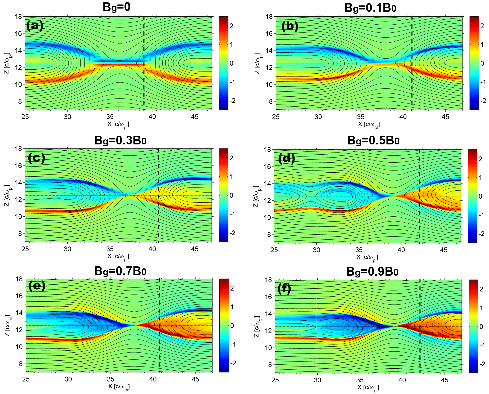
Figure 1The structure of Ez in reconnection with different guide fields (Bg=0, 0.1B0, 0.3B0, 0.5B0, 0.7B0, 0.9B0) at tωci=32 in the x–z plane. Solid black curves display the magnetic field lines. Vertical dashed lines in each panel mark the position of , where δx is the horizontal distance to the X point.
A guide field, which is perpendicular to the reconnection plane (the guide field usually points in the GSM Y direction in the magnetotail), usually exists in reconnection in laboratory, space, and astrophysical plasmas. Many magnetic reconnection events with guide fields in the Earth's magnetotail have been reported. Øieroset et al. (2001) identified an ion diffusion region with a guide field of about 20 % of the field strength in the lobe region. Nakamura et al. (2008) showed that a large guide field (up to 80 % of the lobe field) exists within the magnetic reconnection region. Comparing the simulation results with satellite observation, Eastwood et al. (2010) found that the structure of the diffusion region is altered by a moderate guide field (∼20 % of the lobe field). The Hall electromagnetic fields are asymmetric across the current sheet. Zhou et al. (2014) identified a super-Alfvénic electron jet extended to 30 s ion inertial length away from the X line in a reconnection region with a weak guide field. This jet was deflected from the neutral sheet owing to the Lorentz force jL×Bg; here, jL is the electric current in the outflow direction and Bg is the guide field. In the Earth's magnetopause, component reconnections (with a non-negligible guide field) are suggested as important processes during solar-wind–magnetosphere interactions because the interplanetary magnetic fields (IMFs) have a variety of shear angles relative to the Earth's dipole field (Fuselier et al., 2011).
Although great efforts have been made to understand the guide field reconnection, and we have already known that the Hall magnetic and electric field are distorted in the presence of a guide field, the detailed structure of electric fields in guide field reconnection remains an open question. In this paper, we performed a series 2.5-D particle-in-cell simulation to study the electric field structures within magnetic reconnection in the presence of different guide fields. We focus on the electric fields near the X point. The simulation results show that the conventional bipolar Hall electric field is replaced by a tripolar electric field when a sufficient large guide field is imposed (Bg≥0.3B0), while the conventional bipolar Hall electric field exists only in the small guide field regime. We further analyzed the generalized Ohm law to understand the origin of the new electric field.
Our 2.5-D fully electromagnetic full particle code has been used to study the electric field structures inside the magnetic island, density cavity, and sub-structures of the separatrix near and/or within the magnetic reconnection region (Zhou et al., 2011, 2012a, b, 2014; Huang et al., 2014, 2015). In this model, ions and electrons are regarded as individual particles. The Maxwell equation set is solved to advance the electromagnetic fields, while the Lorentz equation is solved to advance particles.
The initial magnetic field is given by two Harris current sheets: , where B0 is the asymptotic magnetic field amplitude, Lz is the box size in the z direction, and L0 is the initial half-width of the current sheets which is set to 0.5di ( is the initial ion inertial length based on the density n0 in the center of the current sheets). Reconnection occurs in the x–z plane (+x points right and +z points upward; +y points inward in the out-of-plane direction). We apply periodic boundary conditions in the x and z directions for both particles and fields. A small system size flux perturbation is added initially to boost the system entering the nonlinear stage. Details of this model have been discussed in Zhou et al. (2012b).
The simulation box is 50c∕ωpi in the x direction and 50c∕ωpi in the z direction, where c is the speed of light and ωpi is the ion plasma frequency in the central current sheet. The whole simulation box consists of 2000×2000 grids; that is, each grid is equivalent to 0.025c∕ωpi. The magnetic field is normalized by B0, the electric field is normalized by B0VA, the velocity is normalized by VA, and the electric current density is normalized by qn0VA, where q is the unit charge and VA is the Alfvén speed based on B0 and n0. The mass ratio used is . Uniform guide fields with different values are added initially in the −y direction.

For convenience, we selected one of the two current sheets to illustrate our results. Electric fields Ez in the presence of different initial guide fields at tωci=32, when the reconnection rates reach their peak, are displayed in Fig. 1. In the case of a zero guide field, the Hall electric field normal to the current sheet exhibits a typical symmetric bipolar structure (Fig. 1a). When a small guide field (Bg=0.1B0, Fig. 1b) is added in the system, the structure of a Hall electric field becomes asymmetric with respect to the current sheet though the bipolar structure is retained. With the increase in a guide field, thin current layers in the vicinity of the X points deflect toward the separatrix and magnetic islands are generated within the outflow, and sub-structures of the electric field also appear around the separatrix (Fig. 1c–f), i.e., a positive electric field Ez above the upper left separatrix and negative Ez beneath the lower right separatrix. There is only a negative Ez at and near the upper separatrix and positive Ez around the bottom separatrix in the case without a guide field (Fig. 1a). This difference indicates that the guide field brings some new features to electric fields besides causing the asymmetry.
To further illustrate how the guide fields affect the structure of Ez, six profiles of Ez along δx=3di in simulations of different guide fields are shown in Fig. 2. Here δx is the horizontal distance to the X point. Vertical dashed lines in Fig. 1 mark the locations of δx. The red line shows the Ez in the case without a guide field, which exhibits a centrosymmetric bipolar structure with positive Ez below and negative Ez above . Here is the location of a neutral sheet where Bx=0. This is the typical Hall electric field as it is convergent toward the neutral sheet because electrons move faster than the ions (Sonnerup, 1979; Priest and Forbes, 2000). With the increase in the guide field, Ez is no longer centrosymmetric with respect to . Positive Ez occupies a larger area than the negative Ez, and it no longer resides beneath the neutral sheet but extends to above the neutral sheet. This is consistent with Eastwood et al. (2010) in that the Hall electric field is asymmetric and shunted away from the neutral sheet in guide field reconnection. We noticed that there is a small negative excursion of Ez on the left-hand side of the enlarged positive Ez region in the cases with Bg≥0.3B0. Thus, Ez exhibits a tripolar structure instead of a bipolar structure when the initial guide field is larger than 0.3B0. The negative electric field ranges from 10.4 to 11.4 in the case of Bg=0.3B0. It occupies a larger region in the case of Bg=0.5B0. The size of the negative electric field seems to increase with the increment of the guide field. We also noticed that the amplitude of this negative Ez increases with the increment of the guide field, which is further discussed later.
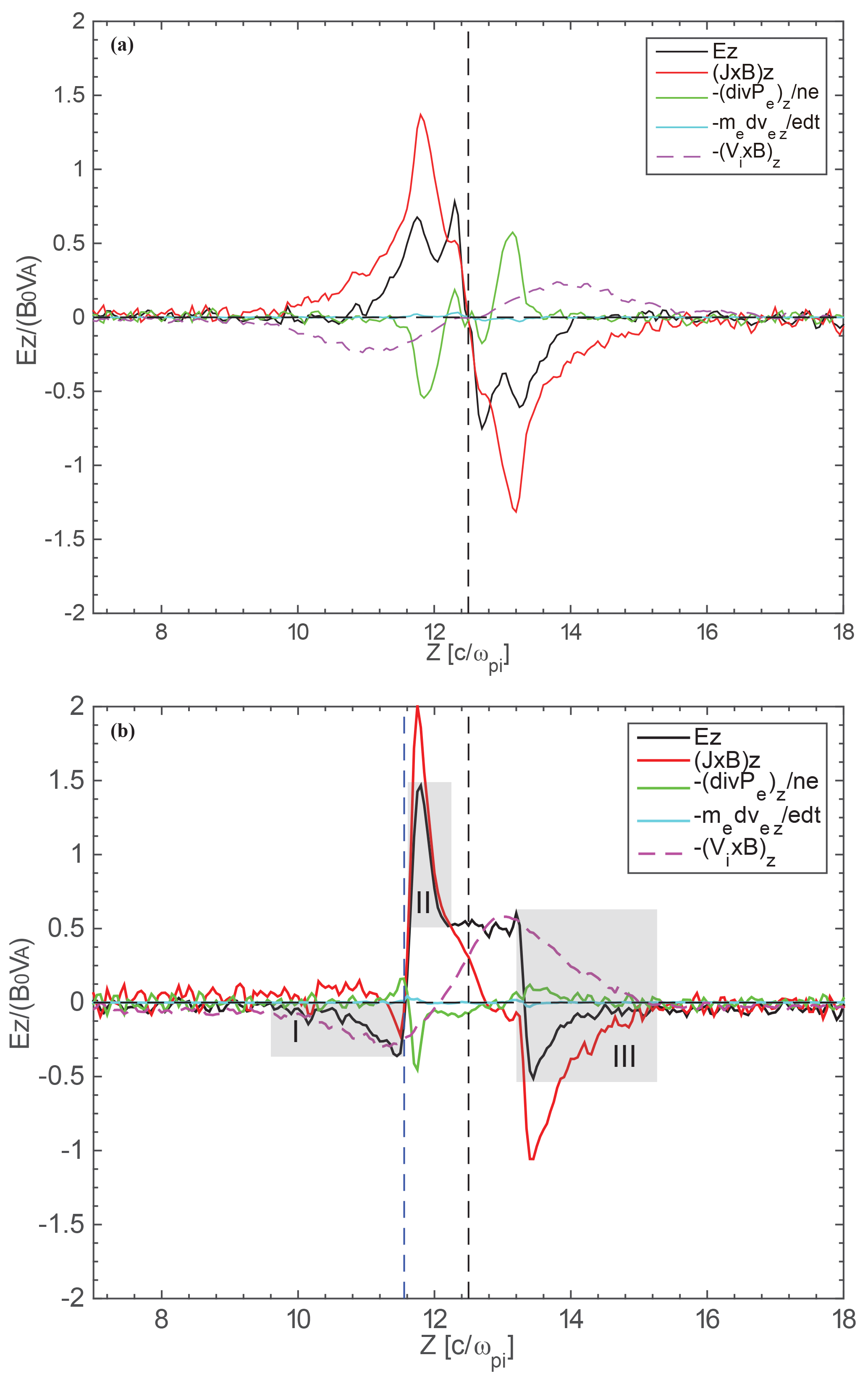
Figure 3The contributions of each term in the generalized Ohm law to Ez. The upper panel shows the result with a zero guide field, while the lower panel shows the results for guide field Bg=0.5B0. The three gray shades in the lower panel mark the three peaks of Ez in guide field reconnection.
To reveal the origin of this negative electric field, we examined the generalized Ohm law:
The terms on the right-hand side (RHS) are the convective term, Hall term, divergence of the electron pressure tensor, electron inertial term, and resistivity term, respectively. The resistivity term is not evaluated in our simulations. In Fig. 3, we depict the relative contribution of each term on the RHS of the above equation to Ez. Upper panel shows the case with a zero guide field, while the lower panel shows the case with guide field Bg=0.5B0. For the zero guide field case, peaks of Ez (at approximately z=11.5, 12.4, 12.6, and 13.5c∕ωpi) are mainly balanced by the Hall terms (red) and the divergences of the electron pressure tensor (green), with the Hall terms dominating. The convective term (purple) is smaller than these two terms around the peak of Ez. For the guide field case, Ez is constituted by different terms in different regions. Ez (black) in regions II and III (marked by the gray shaded area in Fig. 3b) is primarily balanced by the combination of the Hall term, convective term, and divergence of the electron pressure tensor, while in region I, the negative Ez (black) is mainly balanced by the convective term (purple). This implies that this new electric field is a convective electric field instead of a Hall electric field.

Figure 4Subitems of the Hall term (J×B)z. Panels from (a) to (e) display and two components of the Hall term, respectively, for the zero guide field case. Panels from (f) to (j) are similar to (a) to (e) but for the case of guide field Bg=0.5B0. Black dashed lines in each plot mark the neutral sheet, while blue dashed lines in (f) to (j) mark the inflection points of Ez.
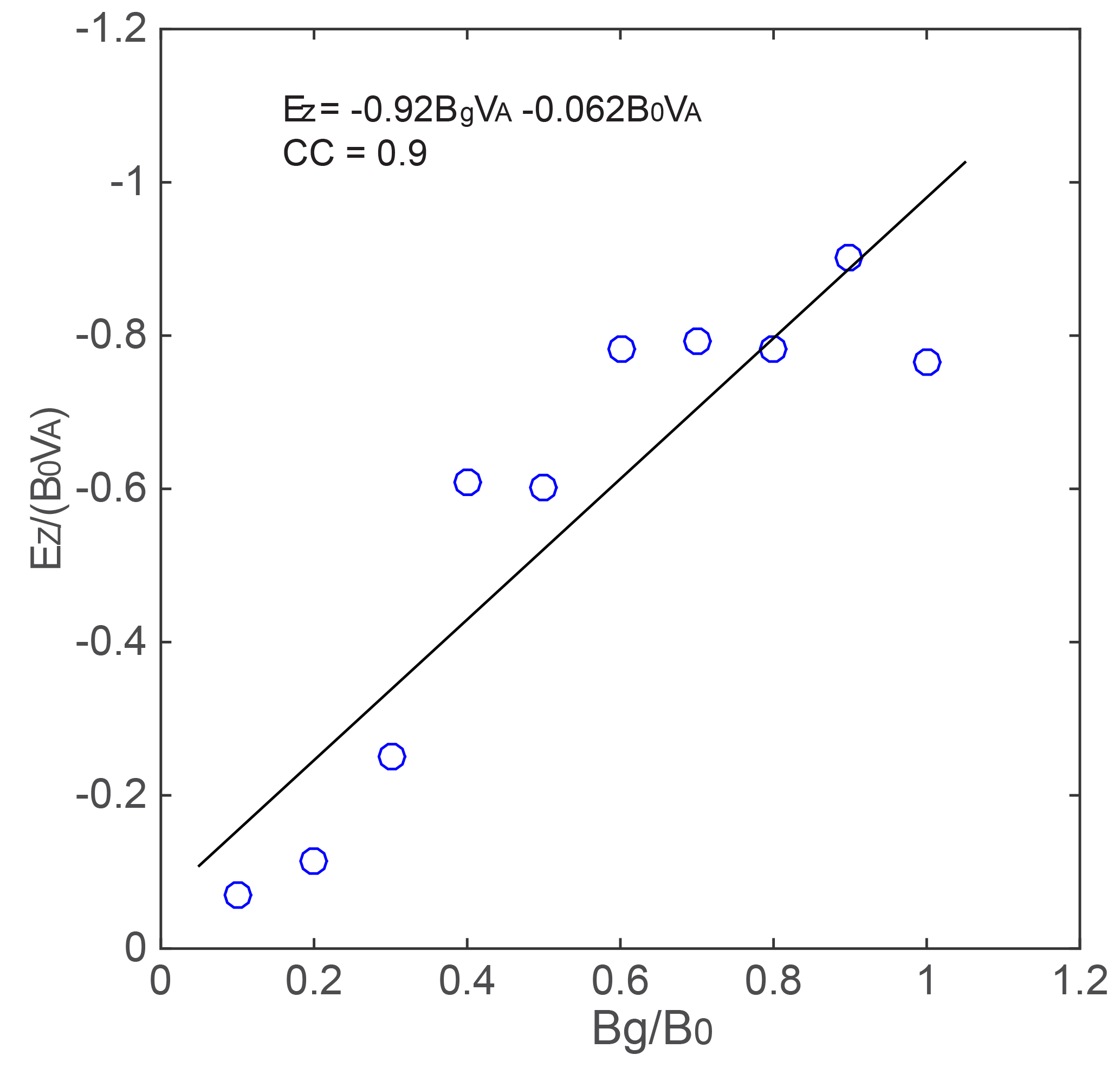
Figure 5The relation between guide field strength and the peak of the newly emerged electric field. The black line indicates the linear fitting by the least square method.
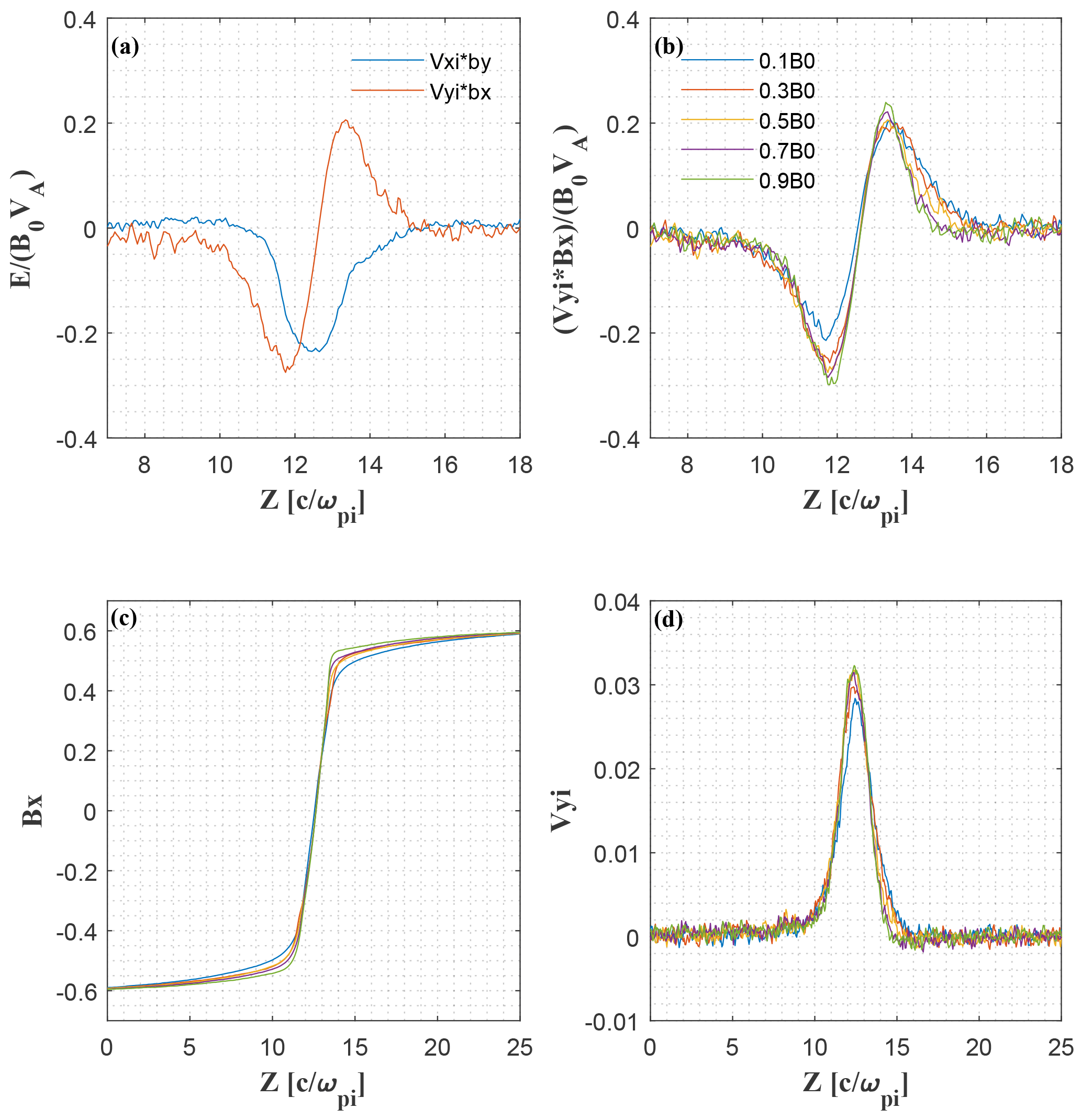
Figure 6Subitems of the convection electric field VyBx−VxBy. (a) VxBy and VyBx for Bg=0.5B0; (b) VyBx for different guide fields; (c) Bx for different guide fields; (d) Vy for different guide fields.
One may ask how the convective electric field emerges in the presence of the guide field. From Fig. 3 one can see that, although the convective term is asymmetric across the neutral sheet in the presence of a guide field, the amplitude does not change too much between the two cases. Nevertheless, the Hall term is substantially different between the two cases. The inflection point (where the Hall term reverses sign) of the Hall term is exactly the same as the inflection point of the convective term in non-guide field reconnection. However, in guide field reconnection, the Hall term is distorted with respect to the neutral sheet. It has been shown that the Hall term is the main factor leading to the distortion of the electric field Ez (Lai et al., 2015). The region with a positive Hall term shrinks compared to the case without a guide field; hence, a region with only a convective term emerges.
In addition, we divide the Hall term into two subitems, i.e., , as is shown in Fig. 4. The electric current density Jx, Jy and the magnetic field Bx, By are also shown in Fig. 4. One can see that the profiles of Bx are more or less similar in both cases, while the other three parameters vary much between the two cases. For the non-guide field case (Fig. 4e), Jy has a bifurcation structure with the minimum current density at the neutral sheet. For the guide field case, Jy has three peaks across the current sheet, with one peak located at Bx=0. Jx reaches its peak around Bx=0 without a guide field, while it moves toward the edge of the current sheet in the guide field case. This is consistent with the result of Zhou et al. (2014) that the outflow electron jet is deflected away from the neutral sheet as a result of the in-plane Lorentz force. The profile of By also varies significantly because of the superposition of the guide field. Therefore, the Hall term also varies much correspondingly. It is mainly provided by JyBx (green) around the peak value, while JxBy (red) is negligible compared to JyBx in the zero guide field case. This is because Jx and By are smaller than Jy and Bx around the peak of the Hall term, the location of which is away from the neutral sheet. In the presence of the guide field (Fig. 4j), the magnitude of JxBy increases significantly compared to the case without a guide field. This is because the imposed uniform guide field Bg and the deflected Jx increase the magnitude of JxBy. The two peaks of JxBy, one of which is around z=13.5 and the other around z=11.6, counterbalance the peaks of JyBx, which reduces the Hall electric field. The latter peak corresponds to the location of the newly emerged electric field.
Figure 5 displays the relation between the guide field Bg and the peak magnitude of the negative electric field Ez at δx=3di. We see that there is roughly a linear relation between guide field and electric field. The correlation coefficient is about −0.9. We fitted the results with a linear equation by the least square method: . This relation can be understood as follows. We have shown that Ez is mainly contributed by the convective term in the generalized Ohm law, i.e., . Figure 6a and b show that the negative Ez is mainly balanced by VyBx, the magnitude of which increases with the increment of guide field strength. The variation of VyBx as a function of Bg is mainly caused by the variation of Bx as shown in Fig. 6c and d. We see that Vy does not vary obviously with the change in the guide field Bg, while Bx at the location of the negative Ez correlates well with Bg; i.e., the larger the , the larger the . This is because the guide field decreases the width of reconnecting current sheet.
Eastwood et al. (2010) have pointed out that the moderate guide field causes considerable asymmetry in the Hall fields. Our simulations show that when there is a moderate guide field, the normal electric field will not only become asymmetric, but also evolve to a tripolar structure; i.e., a new negative electric field emerges. This new electric field is not a Hall electric field, but a convective electric field. It is negative and below the neutral sheet with a negative guide field. We can easily deduce that the new electric field appears above the neutral sheet with a positive value once the guide field is positive. It becomes significant because the Hall electric field in that location is small due to the cancellation of JxBy and JyBx as a result of the enhanced and due to the imposed guide field. The peak magnitude of the new electric field increases linearly with the increment of guide field strength.
Our finding may have applications in space observations. For instance, it may be used to infer the strength of a guide field, which is usually difficult to pinpoint solely from magnetic field measurements. The strength of a guide field is important because it determines the degree of electron magnetization as well as the electron energization efficiency in the vicinity of the diffusion region (Pritchett, 2006; Scudder and Daughton, 2008). With the measurement of this new convective electric field, we may be able to deduce the guide field strength based on the linear relation derived in this study. Hence this could be a supplemental way to infer the guide field strength.
The bipolar normal electric field structure is widely used as evidence of an ion diffusion region in space observations. When a spacecraft crossed the ion diffusion along the normal direction in anti-parallel reconnection, it would observe a bipolar EN field (N is the current sheet normal; in our simulation it is z). However, according to this study, the spacecraft would record a tripolar EN when crossing the ion diffusion region in the presence of a moderate guide field. Therefore, one must be cautious not to eliminate the crossing as a possible ion diffusion region based on the fact that a tripolar but not a bipolar EN field is observed.
Recently Malakit et al. (2013) found a new electric field in asymmetric magnetic reconnection. This electric field is named the “Larmor electric field” because it is associated with the finite ion Larmor radius effect and hence is distinct from the Hall electric field. This electric field is also balanced by the convective term in the generalized Ohm law, which is similar to our simulation. This electric field structure in asymmetric reconnection may be complicated by a guide field, and this issue will be studied in future.
The simulation data will be preserved in a long-term storage system and will be made available upon request to the corresponding author.
The authors declare that they have no conflict of interest.
This work was supported by the National Science Foundation of China (NSFC)
under grants 41704162, 41674161, 41522405, 41774154, and 41331070. The
computations were performed on TianHe-1A at the National Supercomputing
Center (NSCC) in Tianjin. The simulation data can be acquired by contacting
the correspondence author Meng Zhou (mengzhou@ncu.edu.cn).
The topical editor, Minna Palmroth, thanks two anonymous
referees for help in evaluating this paper.
Birn, J., Drake, J. F., Shay, M. A., Rogers, B. N., Denton, R. E., Hesse, M., Kuznetsova, M., Ma, Z. W., Bhattacharjee, A., Otto, A., and Pritchett, P. L.: Geospace Environment Modeling (GEM) reconnection challenge, J. Geophys. Res., 106, 3715–3719, https://doi.org/10.1029/1999JA900449, 2001.
Deng, X. H. and Matsumoto, H.: Rapid magnetic reconnection in the Earth's magnetosphere mediated by whistler waves, Nature, 410, 557–560, https://doi.org/10.1038/35069018, 2001.
Eastwood, J. P., Shay, M. A., Phan, T. D., and Øieroset, M.: Asymmetry of the ion diffusion region Hall electric and magnetic fields during guide field reconnection: Observations and comparison with simulations, Phys. Rev. Lett., 104, 205501, https://doi.org/10.1103/PhysRevLett.104.205001, 2010.
Fuselier, S. A., Trattner, K. J., and Petrinec, S. M.: Antiparallel and component reconnection at the dayside magnetopause, J. Geophys. Res., 116, A10227, https://doi.org/10.1029/2011JA016888, 2011.
Huang, S. Y., Zhou, M., Sahraoui, F., Deng, X. H., Pang, Y., Yuan, Z. G., Wei, Q., Wang, J. F., and Zhou, X. M.: Wave properties in the magnetic reconnection diffusion region with high β: Application of the k-filtering method to Cluster multispacecraft data, J. Geophys. Res., 115, A12211, https://doi.org/10.1029/2010JA015335, 2010.
Huang, S. Y., Vaivads, A., Khotyaintsev, Y. V., Zhou, M., Fu, H., Retinò, A., Deng, X. H., André, M., Cully, C. M., He, J., Sahraoui, F., Yuan, Z., and Pang, Y.: Electron Acceleration in the Reconnection Diffusion Region: Cluster Observations, Geophys. Res. Lett., 39, L11103, https://doi.org/10.1029/2012GL051946, 2012.
Huang, S. Y., Zhou, M., Yuan, Z. G., Deng, X. H., Sahraoui, F., Pang, Y., and Fu, S.: Kinetic simulations of electric field structure within magnetic island during magnetic reconnection and their applications to the satellite observations, J. Geophys. Res.-Space Phys., 119, 7402–7412, https://doi.org/10.1002/2014JA020054, 2014.
Huang, S. Y., Zhou, M., Yuan, Z. G., Fu, H. S., He, J. S., Sahraoui, F., Aunai, N., Deng, X. H., Fu, S., Pang, Y., and Wang, D. D.: Kinetic simulations of secondary reconnection in the reconnection jet, J. Geophys. Res.-Space Phys., 120, 6188–6198, https://doi.org/10.1002/2014JA020969, 2015.
Lai, X., Zhou, M., Deng, X., Li, T., and Huang, S.: How Does the Guide Field Affect the Asymmetry of Hall Magnetic and Electric Fields in Fast Magnetic Reconnection?, Chin. Phys. Lett., 32, 095202, https://doi.org/10.1088/0256-307X/32/9/095202, 2015.
Malakit, K., Shay, M. A., Cassak, P. A., and Ruffolo, D.: New Electric Field in Asymmetric Magnetic Reconnection, Phys. Rev. Lett., 111, 135001, https://doi.org/10.1103/PhysRevLett.111.135001, 2013.
Nakamura, R., Baumjohann, W., Fujimoto, M., Asano, Y., Runov, A., Owen, C. J., Fazakerley, A. N., Klecker, B., Rème, H., Lucek, E. A., Andre, M., and Khotyaintsev, Y.: Cluster observations of an ion-scale current sheet in the magnetotail under the presence of a guide field, J. Geophys. Res., 113, A07S16, https://doi.org/10.1029/2007JA012760, 2008.
Øieroset, M., Phan, T. D., Fujimoto, M., Lin, R. P., and Lepping, R. P.: In situ detection of collisionless reconnection in the Earth's magnetotail, Nature, 412, 414–417, https://doi.org/10.1038/35086520, 2001.
Paschmann, G., Øieroset, M., and Phan, T.: In-situ observations of reconnection in space, Space Sci. Rev., 178, 385–417, https://doi.org/10.1007/s11214-012-9957-2, 2013.
Priest, E. and Forbes, T.: Magnetic Reconnection: MHD Theory and Applications, Cambridge Univ. Press, Cambridge, UK, 2000.
Pritchett, P. L.: Relativistic electron production during guide field magnetic reconnection, J. Geophys. Res., 111, A10212, https://doi.org/10.1029/2006JA011793, 2006.
Scudder, J. and Daughton, W.: “Illuminating” electron diffusion regions of collisionless magnetic reconnectionusing electron agyrotropy, J. Geophys. Res., 113, A06222, https://doi.org/10.1029/2008JA013035, 2008.
Sonnerup, B. U. Ö.: Magnetic field reconnection, in: Solar System Plasma Physics, edited by: Lanzerotti, L. J., Kennel, C. F., and Parker, E. N., p. 46, North Holland Publ., Amsterdam, 1979.
Yamada, M., Kulsrud, R., and Ji, H.: Magnetic reconnection, Rev. Mod. Phys., 82, 603–664, https://doi.org/10.1103/RevModPhys.82.603, 2010.
Zhou, M., Pang, Y., Deng, X. H., Yuan, Z. G., and Huang, S. Y.: Density cavity in magnetic reconnection diffusion region in the presence of guide field, J. Geophys. Res., 116, A06222, https://doi.org/10.1029/2010JA016324, 2011.
Zhou, M., Deng, X. H., and Huang, S. Y.: Electric field structure inside the secondary island in the reconnection diffusion region, Phys. Plasmas, 19, 042902, https://doi.org/10.1063/1.3700194, 2012a.
Zhou, M., Deng, X. H., Pang, Y., Huang, S. Y., Yuan, Z. G., Li, H. M., Xu, X. J., Wang, Y. H., Yao, M., and Wang, D. D.: Revealing the sub-structures of the magnetic reconnection separatrix via particle-in-cell simulation, Phys. Plasmas, 19, 072907, https://doi.org/10.1063/1.4739283, 2012b.
Zhou, M., Pang, Y., Deng, X., Huang, S., and Lai, X.: Plasma physics of magnetic island coalescence during magnetic reconnection, J. Geophys. Res.-Space Phys., 119, 6177–6189, https://doi.org/10.1002/2013JA019483, 2014.