the Creative Commons Attribution 4.0 License.
the Creative Commons Attribution 4.0 License.
PPP-based Swarm kinematic orbit determination
Le Ren
Steffen Schön
The Swarm mission of the European Space Agency (ESA) offers excellent opportunities to study the ionosphere and to provide temporal gravity field information for the gap between the Gravity Recovery and Climate Experiment (GRACE) and its follow-on mission (GRACE-FO). In order to contribute to these studies, at the Institut für Erdmessung (IfE) Hannover, a software based on precise point positioning (PPP) batch least-squares adjustment is developed for kinematic orbit determination. In this paper, the main achievements are presented.
The approach for the detection and repair of cycle slips caused by ionospheric scintillation is introduced, which is based on the Melbourne–Wübbena and ionosphere-free linear combination. The results show that around 95 % of cycle slips can be repaired and the majority of the cycle slips occur on L2. After the analysis and careful preprocessing of the observations, 1-year kinematic orbits of Swarm satellites from September 2015 to August 2016 are computed with the PPP approach. The kinematic orbits are validated with the reduced-dynamic orbits published by the ESA in the Swarm Level 2 products and SLR measurements. The differences between IfE kinematic orbits and ESA reduced-dynamic orbits are at the 1.5, 1.5 and 2.5 cm level in the along-track, cross-track and radial directions, respectively. Remaining systematics are characterized by spectral analyses, showing once-per-revolution period. The external validation with SLR measurements shows RMSEs at the 4 cm level. Finally, fully populated covariance matrices of the kinematic orbits obtained from the least-squares adjustment with 30, 10 and 1 s data rate are discussed. It is shown that for data rates larger than 10 s, the correlation between satellite positions should be taken into account, for example, for the recovery of gravity field from kinematic orbits.
- Article
(16589 KB) - Full-text XML
- BibTeX
- EndNote
The Swarm mission was launched on 22 November 2013 and is the first constellation of satellites of the European Space Agency (ESA) to study the dynamics of the Earth's magnetic field and its interaction with the Earth system (Friis-Christensen et al., 2008). This mission consists of three identical satellites in near-polar low Earth orbits (LEO). The two satellites, Swarm A and C, fly almost side-by-side at an initial altitude of 460 km while the third Swarm satellite B flies in a higher orbit of about 530 km. All the three satellites are equipped with a set of six core instruments: Absolute Scalar Magnetometer (ASM), Vector Field Magnetometer (VFM), Electric Field Instrument (EFI), Star Tracker (STR), Accelerometer (ACC) and GPS Receiver (GPSR). In order to take full advantage of the data information provided by this constellation, Precise Orbit Determination (POD) is necessary, which is obtained with data from the high precision eight-channel dual-frequency GPS receiver. In addition, each satellite has a laser retro-reflector, which makes the independent validation of the GPS-derived orbits with satellite laser ranging (SLR) possible. In recent years, kinematic orbit determination has attracted much attention (Jäggi et al., 2016; Zehentner and Mayer-Gürr, 2015; Švehla and Rothacher, 2003). Compared to the reduced-dynamic approach, the kinematic approach is a purely geometrical approach without using any information on LEO satellite dynamics (e.g. gravity field, air drag, etc.). Therefore, kinematic orbits are preferred for independent gravity field determination.
A first performance evaluation of the RUAG 8-channel GPS receiver was carried out by Zangerl et al. (2014), showing unexpected results and loss of lock due to ionospheric scintillations. Buchert et al. (2015) and Xiong et al. (2016) empirically linked the loss of the GPS signal to ionospheric plasma irregularities. Results from more than 1 year of data using reduced-dynamic and kinematic approaches were reported in van den IJssel et al. (2015) and Jäggi et al. (2016). A comparison with SLR allows an assessment of the orbit accuracy of about 2.5 cm rms for ESA reduced-dynamic orbits and 4 cm for ESA kinematic orbits. The 3-D differences between the reduced-dynamic and kinematic orbits are at the 4–5 cm level, with larger differences close to the geomagnetic poles and along the geomagnetic Equator (van den IJssel et al., 2015). An azimuth and elevation dependent PCV map is generated during flight using the residual approach (Jäggi et al., 2016; van den IJssel et al., 2015). In order to collect more observations and improve the robustness under ionospheric scintillation, the receiver settings have been adjusted several times during the Swarm mission. The impact of the first update on POD performance is analysed in van den IJssel et al. (2016), showing that a lower GPS elevation cut-off angle and wider bandwidths of the tracking loops improve the performance for both orbit types. Gravity field recovery also benefits from the update (Dahle et al., 2017).
In this contribution, the developments for kinematic POD of Swarm satellites at the Institut für Erdmessung (IfE) are reported. This approach is based on the precise point positioning (PPP) technique (Zumberge et al., 1997). This differs from the raw measurements approach by the Institute of Geodesy (IfG) of TU Graz (Zehentner and Mayer-Gürr, 2015), phase-only approach by the Astronomical Institute of University Bern (AIUB) (Jäggi et al., 2016) or the Bayesian weighted least-squares estimator, which is implemented in the GPS High-precision Orbit Determination Software Tools (GHOST) developed at the Deutsches Zentrum für Luft- und Raumfahrt in close cooperation with TU Delft and used for the ESA official orbits (van den IJssel et al., 2015).
Since the GPS data quality is decisive for the obtainable orbit accuracy, we first analyse the in-flight performance of the Swarm onboard GPS receivers in Sect. 2, e.g. the tracking performance and observation noise, especially under the influence of ionospheric scintillation. A mandatory step in the preprocessing is detecting and, if possible, repairing the cycle slips in carrier phase observations in order to reduce the number of ambiguities and therefore strengthen the orbit. Due to the large phase noise caused by ionospheric scintillations, cycle slips in Swarm receivers are difficult to detect at ionospheric-active areas. An approach based on the Melbourne–Wübbena and ionosphere-free linear combination is introduced for this task. In Sect. 3, we introduce the adopted method and models for precise kinematic orbit determination by PPP in a least-squares adjustment. The obtained orbit as well as its fully populated formal covariance matrix are presented. Unlike the CHAllenging Minisatellite Payload (CHAMP) or the Gravity Recovery and Climate Experiment (GRACE), the Swarm GPS receiver provides observations every second since 15 July 2014, which gives us the opportunity to study the temporal correlation of the coordinates with 1 s observation rate. The kinematic orbits are compared with the ESA reduced-dynamic orbits and SLR measurements. Thanks to a more strict data screening strategy and cycle-slip detection, our kinematic orbits show a smaller RMSE compared to ESA kinematic orbits. Section 4 gives a short conclusion of this paper.
Being a purely geometrical approach without using any dynamic models on LEO satellites, the quality of the kinematic orbits relies completely on the GPS observations as well as on the introduced GPS orbit and clock products, and it is sensitive to measurement errors and the observation geometry (Švehla and Rothacher, 2003). High-quality data is the prerequisite for precise kinematic orbits. Therefore, in this section, we first analyse the Swarm GPS receiver data quality and introduce our approach for cycle-slip detection and repair as well as outlier screening.
2.1 Tracking performance
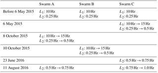
The Swarm onboard dual-frequency GPS receivers are developed by RUAG Space (Zangerl et al., 2014). They have 8 channels for tracking GPS satellites, which is less than the GRACE and Gravity field and steady-state Ocean Circulation Explorer (GOCE) receivers, with 10 and 12 channels, respectively. In order to collect more observations, the field of view was increased step by step from 10∘ elevation cut-off angle at the beginning of the mission to 2∘ cut-off angle since 6 May 2015 for all three Swarm satellites (van den IJssel et al., 2015). Several updates on the bandwidth of the tracking loops were applied to improve the robustness of the tracking in difficult environmental situations. The fast reacquisition of the L1-carrier tracking was enabled by raising the retry counter from zero to five (ESA, 2015). These updates are shortly summarized in Table 1 (Dahle et al., 2017).
The daily average number of tracked GPS satellites was increased from 7.6 to 7.7 after the first update of receiver bandwidth (van den IJssel et al., 2016). For LEO satellites, the number of satellites in view is usually larger than 8. But due to the limitation of receiver channels, only 8 GPS satellites maximum can be tracked. There are two reasons for epochs within which less than 7 GPS satellites are tracked.
The first reason is the reacquisition time of the Swarm receiver. When a GPS satellite sets, the receiver cannot immediately track another GPS satellite in view and needs around 84 s before the first receiver update (red) and 55 s after the update to acquire another satellite (blue), shown in Fig. 1a, for example, for DoY 250, 2015. Thus, during the reacquisition phase, the number of satellites is less than 8. If some satellites set during short time together, the number of tracked satellites is even less than 7. This shortened reacquisition time is also the main reason for the increased number of tracked GPS satellites.
Another reason for tracking less than 7 GPS satellites is the loss of the lock of signal. There are also two reasons for the loss of the GPS signal, and one is due to the weak signal strength for the GPS satellites at low elevations. However, the loss of lock on GPS satellites at high elevations occurs mainly at polar and equatorial areas under the influence of ionospheric scintillations, which is evidenced by the change of the Total Electron Content (TEC). The occurrence of loss of lock in September 2015 is shown in Fig. 1b, for example.
Although the amount of the loss of lock on GPS satellites at higher elevations was decreased from 37 to 11 after the update, the receiver becomes unstable for the signals from lower elevations. The amount of the loss of lock increased almost fourfold, from 58 to 256. The reacquisition time in this situation was decreased from around 17 to 11 s after the update.
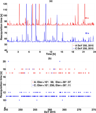
Figure 1Reduction of reacquisition time for Swarm GPS receivers (a) due to setting and rising satellites on DoY 250, 2015 and (b) due to loss of lock in September 2015, red for Swarm A and blue for Swarm C with different tracking settings.

Figure 2(a)P1 code noise with respect to elevation for Swarm A on DoY 100 before fixing the RINEX converter issue and (b) DoY 104, 2016 after fixing the issue.
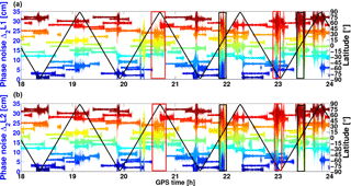
Figure 3(a)Δ2L1 and (b)Δ2L2 noise for Swam A from 18:00 to 24:00 on DoY, 333, 2015, colour coded per PRN (from blue PRN1 to red PRN 32). The time series are intentionally shifted by PRN × 1 cm. The local time is 08:30 for the descending arc and 20:30 for the ascending arc. The right legend shows the geographic latitude.
2.2 Observation analysis
As a dual-frequency receiver, the Swarm GPS receiver provides code observations C∕A (C1C), P1 (C1P) and P2 (C2P) and carrier phase observations L1 (L1C) and L2 (L2P) in the Swarm Level 1b product in the RINEX 3.0 format. A solid analysis of the observation noise is mandatory for an adequate stochastic model. Typically, models have identical weights or elevation dependent weights, e.g. 1∕sin(Elev) or . The code accuracy is analysed with the multipath linear combination (Estey and Meertens, 1999), which contains multipath effects, ambiguities, code and phase noise. Since carrier phase noise is smaller than code noise by two or three orders of magnitude, it can be neglected. Ambiguities are subtracted as mean value. Then, only code noise and multipath effects remain.
Due to a software issue in the RINEX converter (ESA, 2016), the code observations in the Level 1b product before 11 April 2016 (DoY 102) suffer from high noise. The P1 code noise for all the GPS satellites with respect to the elevation for Swarm A on DoY 100, 2016 and DoY 104, 2016 is shown in Fig. 2 as an example. A large code noise of about 1.3 m (1σ) can be seen in the left figure even at high elevations, which is caused by the software issue. After fixing the converter issue, the code noise shows a strong elevation-dependence. The P1 code is disturbed by noise of about 0.8 m (1σ) for satellites at elevations lower than 15∘. The noise is smaller than 0.2 m (1σ) for the satellites above 30∘. A 1∕sin(Elev) curve is used here to approximate the noise behaviour. The standard deviations (1σ) of C∕A code and P2 code for the satellites above 15∘ are around 0.33 m and 0.21 m, respectively, after fixing the converter issue. The C∕A code noise measured onboard based on 1 Hz data rate is twice larger than the noise (0.16 m) measured on the ground with double-differences on a zero baseline experiment (i.e. two receivers are connected to one antenna via a signal splitter, but averaged over 10 s), reported in Zangerl et al. (2014). The P2 code noise with 0.21 m onboard is smaller than the noise in the on-the-ground test with 0.31 m.
The quality of the kinematic orbit determination depends mainly on the available dual-frequency carrier phase observations. To analyse the phase noise, the second-order differences () of successive phase observations are used after removing the geometric distances, which are computed with the Swarm Level 2 reduced-dynamic orbits. The receiver-clock offset and drift is removed during differencing. Due to the differencing process involved, this is a qualitative evaluation method rather than a quantitative one.
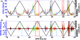
Figure 4(a)STEC and (b)its rate for Swam A from 18:00 to 24:00 on DoY, 333, 2015. The right legend shows the geographic latitude.

Figure 5Carrier phase noise for Δ2L1 and Δ2L2 at midlatitude areas on DoY 333, 2015, plotted against elevation.
The resulting Δ2L1 and Δ2L2 phase time series of Swarm A from 18:00 to 24:00 in the GPS time system on DoY 333, 2015 for all the GPS satellites are shown in Fig. 3 with respect to time. In addition, the geographic latitude is given. In order to know whether the phase observations are influenced by ionospheric scintillations, the absolute slant total electron content (STECF), which is defined as integrated electron density along the line of sight from Swarm to GPS satellites and provided in the Swarm Level 2 product, with its rate at Swarm A is shown in Fig. 4. The absolute STEC is derived from the geometry-free linear combination of L1 and L2, after corrections for differential code biases of GPS satellite transmitters and Swarm receivers (Swarm TEC Product, 2017).
Figures 3 and 4 highlight the variability of the phase noise with respect to the rate of STEC. Carrier phases on both frequencies are simultaneously disturbed under the influence of ionospheric scintillations for all GPS satellites, even at high elevations. Similar large fluctuations also exist in the second-order differences of the ionosphere-free linear combination Δ2L3. The widening of the carrier tracking loops during the updates reduces the impact of ionospheric fluctuations significantly (van den IJssel et al., 2016). The large phase noise, even at decimeter level, can almost always be found at high geographic latitude areas (above 60∘, see red boxes in Fig. 3), for example, where the STEC is low but varies rapidly. At midlatitude areas (20–60∘), the ionosphere is less active, and these effects are rare. At equatorial areas, the impact depends on the local time and the activity of the local ionosphere. Exemplarily, from 18:00 to 20:00, the STEC is high but changes slowly, which does not disturb the phase observations much. On the contrary, after 20:00 in ascending arcs, with local time around 20:30 after sunset, the changes in STEC are rapid and the phase observations are strongly perturbed (compare black boxes in Fig. 3). This large noise degrades the accuracy of the kinematic orbit significantly and makes it difficult to detect small cycle slips with standard methods.
The Δ2L1 and Δ2L2 phase noise at midlatitude areas with respect to elevation is shown in Fig. 5. At a low level of ionospheric activity, the phase noise can reach mm level and the noise on L1 is slightly lower than on L2. The standard deviations (1σ) of Δ2L1 and Δ2L2 are 3.9 and 4.2 mm, respectively. There is no strong dependence on the elevation. Assuming independent observations, the standard deviation (1σ) of the undifferenced phase observations can be assessed to be about 1.6 mm for L1 and 1.7 mm for L2, according to the laws of error propagation.
2.3 Cycle-slip detection and repair
Strong ionospheric scintillations cause not only large noise but also cycle slips in the carrier phase observations. Therefore, a proper cycle-slip detection is necessary to set up correctly the ambiguities. Since the typical GPS satellite visibility for LEOs is mostly 40 min, the necessity of estimating additional ambiguities for even shorter segments will further decrease the geometric strength of the positioning.
A classical method for cycle-slip detection is to use the TurboEdit method (Blewitt, 1993) based on the Melbourne–Wübbena linear combination (Melbourne, 1985; Wübbena, 1985). This is represented as
where LMW represents the Melbourne–Wübbena linear combination, f1 and f2 the carrier frequency, L1 and L2 the carrier phase observation in meters, b1 and b2 the ambiguities and λw the wide-lane wavelength.
However, the code observations before DoY 102, 2016 contain large noise due to the RINEX converter issue (ESA, 2016), see Fig. 2. The corresponding standard deviation (1σ) of the Melbourne–Wübbena combination is about 0.8 cycles (wide-lane wavelength). The threshold used in the TurboEdit method for the cycle-slip detection is typically 4σ, which means that cycle slips smaller than 3 cycles cannot be detected, see Fig. 6a.
Thus, a forward and backward moving window averaging (FBMWA) method is applied to reduce the influence of large noise (Cai et al., 2013). In this algorithm, the wide-lane ambiguity is smoothed in both forward and backward directions with a specified size m of the smoothing window in each direction. This differs from the regular TurboEdit algorithm, where only the backward smoothing is performed and the window size continuously grows with the number of epochs. For Swarm satellites, m is set as 50 in order to reduce the noise of wide-lane ambiguity to 0.1 cycles. For example, PRN23 is shown in Fig. 6b, the cycle slip is the difference between the forward moving window average at epoch k and the backward moving window average at epoch k−1, which is represented as follows:
where Δ is the operator for epoch differencing, and c1=1 can be identified in the peak close to an integer (difference smaller than 0.1) in the black curve in this example.
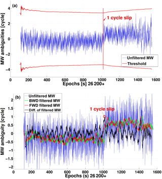
Figure 6Illustration of the proposed cycle-slip detection approach based on Melbourne–Wübbena combination, PRN23 of Swarm A on DoY 333, 2015: (a) TurboEdit method, the cycle slip cannot be detected; (b) FBMWA (forward and backward moving window averaging) method .
Since with the Melbourne–Wübbena linear combination only the difference of cycle slips on L1 and L2 can be detected and simultaneous occurring of same magnitude cycle slips on L1 and L2 are not detectable, another linear combination is still required, in order to determine the cycle slips on both frequencies and repair them. Due to the rapid variations of the ionospheric delays and the large phase noise at ionosphere active areas, the geometry-free linear combination is not suitable for Swarm receivers. Here, the time-differenced ionosphere-free linear combination after removing the difference of geometric distances and receiver-clock errors is thus used so that the rapid and large variations of the ionospheric delay can be avoided. This can be represented by the following:
where L3 represents the ionosphere-free combination of carrier phase (other observation errors are corrected), ρ the geometric distance between GPS satellite and receiver position, and δtr the receiver-clock error in meters where the coefficients before Δb1 and Δb2 are approximately 0.4844 and 0.3775 m, respectively.
The geometric distances are computed with the Medium Precise Orbit (MEO) provided by ESA in the Swarm Level 1b product and removed from the right-hand side of Eq. (3). The prerequisite for this approach is that there is no large jump in the a priori orbit.
After removing the geometric distances term, the differences of receiver-clock error and ambiguity on L1 and L2 still remain. If there is no cycle slip in the carrier phase, the ambiguity term should be similar to zero-mean white noise and the difference of receiver-clock error can be computed as the average over all tracked GPS satellites, as it is the same for all receiver channels. If there are cycle slips for one GPS satellite, the deviation between the average and this satellite is much larger than the other normal satellites. So the satellite with cycle slips can be detected and the difference of receiver-clock error should be computed again without this one until no large deviation can be found and removed from the right-hand side of Eq. (3).
After removing the geometric distances and receiver-clock error, only the ambiguity term remains. If there is no cycle slip, the ΔL3 time series spreads around zero in accordance with the phase noise. When a cycle slip occurs, a large jump occurs in the time series. In order to determine the cycle slip exactly and distinguish it from outliers, this jump should be computed as accurately as possible. Instead of calculating the epoch difference of two successive epochs (Fig. 7a), the epoch difference of two epochs separated by n epochs (Fig. 7b) are calculated and then the mean value of these n-epochs differences is formed so that the influence of the large noise under ionospheric scintillation can be reduced (see Fig. 7b). Considering the large noise of ionosphere-free linear combination under ionospheric scintillations (around 10 cm), we propose to select n=100 in order to reduce the noise to 1 cm level. Taking the example of PRN23, we can calculate the following: , here c2≈0.38 m.
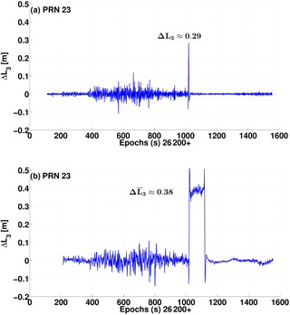
Figure 7Illustration of the proposed cycle-slip detection approach based on an ionosphere-free linear combination from PRN23 of Swarm A on DoY 333, 2015. The following are shown: (a) ΔL3 between two successive epochs and (b) ΔL3 between two epochs separated by 100 epochs .
Together with the equation from Melbourne–Wübbena linear combination, the cycle slip on L1 and L2 can be determined:
In this example we can calculate the following: and . If the difference of Δb1 to its nearest integer is smaller than 0.2, it can be rounded and marked as “repaired”.
The statistics of the repaired cycle slips for Swarm satellites during 1 year from DoY 245, 2015 to DoY 244, 2016 are listed in Table 2. Around 95 % of the cycle slips could be repaired. Issues occur by rapid sequences of cycle slips in short time due to strong ionospheric scintillations. The observations during this period can be excluded as outliers. The majority of the cycle slips occur on L2. The worldwide distribution of the cycle slips are shown in Fig. 8a. As expected, their occurrence is linked with ionosphere active regions such as polar and equatorial areas. Because of a higher orbit (530 km) where the ionosphere is weaker than at the lower orbit (450 km), the number of cycle slips on Swarm B is less than for Swarm A and C. Due to the similar atmosphere around Swarm A and C, they suffer from the cycle slips almost at the same time. Significantly more cycle slips are found around the geomagnetic South Pole than around the North Pole. The reasons are still under investigation.
Table 2Statistics of the cycle slips for Swarm A, B and C during 1 year from DoY 245, 2015 to DoY 244, 2016

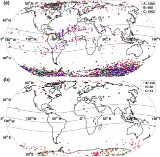
Figure 8Global distribution of cycle slips on Swarm A (red), B (green) and C (blue) (a) from DoY 245, 2015 to DoY 244, 2016 and (b) from September 2015. The black lines are the geomagnetic Equator and geomagnetic parallel of ±20∘. The results are given in Table 2.
In order to see the impact of update of bandwidth of the tracking loop, the cycle slips in September 2015 are additionally shown in Fig. 8b. It can be seen that the number of cycle slips are significantly reduced after the update in May 2015 on Swarm C. Because the ionosphere has been very weak since May 2016, the tracking is very stable. There were just a few cycle slips, so the impact of the update in June and August 2016 cannot be observed.
2.4 Outlier detection
As a purely geometric approach, the kinematic orbit is sensitive to the GPS measurement errors. As a consequence, it is important to screen the outliers. The epoch-differenced ionosphere-free linear combination ΔL3 used in cycle-slip detection can also be used to detect the outliers. Considering that the L3 noise under ionospheric scintillation can reach the 10 cm level, if ΔL3 is larger than 20 cm, an outlier is detected and should be eliminated. Some systematic errors can also be detected with it. For cases where the orbit of a given GPS satellite is not accurate enough, the time series of ΔL3 of the corresponding GPS satellite will not be zero-mean but will show a strong trend. Thus, to avoid a systematic error in the LEO orbit and carrier phase residuals, the corresponding satellites have to be removed accordingly. This can be seen in Fig. 9 for PRN 26 (purple) and PRN 32 (green). Such satellites can be found in the IGS weekly summary (e.g. ftp://ftp.igs.org/pub/product/1864/igs18647.sum.Z, last access: 17 September 2018). After removing these satellites, the quality of the kinematic orbits is significantly improved. The same effects can also be found on Swarm C at the same time.
In this section, the approach for kinematic orbit determination at IfE will be introduced first. Then 1-year kinematic Swarm orbits are validated with the reduced-dynamic orbits and the SLR residuals. The fully populated variance–covariance matrices of the kinematic orbits obtained from the adjustment are shown and discussed.
3.1 Observation modelling
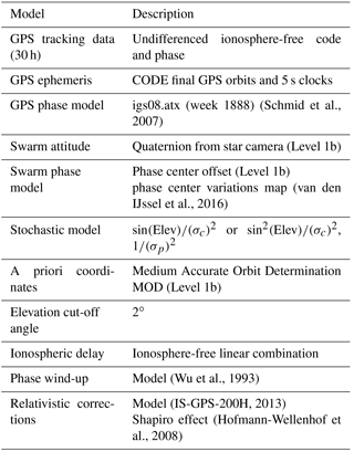
A MATLAB-based PPP software was developed at IfE Hannover using the least-squares adjustment method. The ionosphere-free linear combinations of P code and phase are computed and introduced as observables in the least-squares adjustment model to eliminate the first-order ionospheric effect. The GPS orbits and satellite clock errors are computed based on the CODE final GPS orbits and 5 s clock products provided by the Center for Orbit Determination in Europe (CODE) (Bock et al., 2009; Dach et al., 2016). The observation and error modelling used for the kinematic orbit determination is listed in Table 3.
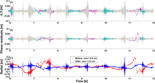
Figure 9Outlier detection and anomalous GPS satellite for Swarm A on DoY 271, 2015, here PRN26 (purple) and PRN32 (green); (a) ΔL3 between epochs separated by 100 s, (b) phase residuals and (c) deviations of the kinematic orbit with respect to ESA reduced-dynamic orbits with (red) or without (blue) the anomalous GPS satellites.
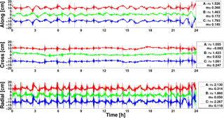
Figure 10Position residuals for Swarm A (red), B (green) and C (blue) with respect to ESA reduced-dynamic orbits for DoY 333, 2015. The time series are offset by 10 cm for Swarm A and C. The legend indicates the rms (r) and mean value (m) in cm.
The 1 Hz data is processed over 30 h, with 3 h overlap in the previous and following day. In this way, the removal of some GPS observations can be avoided due to the short arc at the day boundary. This increases the stability of the ambiguities at the day boundary. Because the observation time saved in the RINEX file is synchronized to the receiver internal clock, which has a large clock drift, a time offset is added to synchronize the internal clock with GPS time everyday at the day boundary. This causes a clock jump in the code observations and a clock jump as well as a phase jump in the carrier phase observations. In order to get a continuous arc at the day boundary, these phase jumps need to be fixed. The clock jump is first determined from the average of each epoch-differenced code observations (removing the a priori geometric distances) at the day boundary. Then, the phase jump is the average of each epoch-differenced phase observations (removing the a priori geometric distances) minus the clock jump.
The phase noise is weakly elevation-dependent (see Fig. 5) and an identical weight matrix is thus applied to phase observations. The code noise has a stronger elevation-dependent behaviour after fixing the converter issue. Therefore, a sine-squared elevation-dependent weight matrix is applied to code observations after fixing instead of a sine elevation-dependent weight matrix before fixing. The variances are selected with 6 m (before fixing the converter issue)/0.6 m (after fixing the converter issue) for the code and 6 mm for the carrier phase according to the investigation described in Sect. 2, taking the error propagation for the ionosphere-free linear combination into account and considering the phase noise under ionospheric scintillation. Accordingly, the weight matrix per epoch has a diagonal structure.
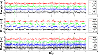
Figure 11Differences of kinematic orbits with respect to ESA reduced-dynamic orbits of Swarm C of different institutes from DoY 1 to 7, 2016. The time series are intentionally shifted by 15, 5, −5 and −15 cm for AIUB (red), IfG (green), ESA (blue) and IfE (black), respectively. The legend gives the rms in cm.
Table 4rms and mean of position residuals of IfE and ESA kinematic orbits with respect to ESA reduced-dynamic orbits for Swarm A, B and C during 1 year (DoY 245, 2015 to DoY 244, 2016). The values for ESA kinematic orbits are given in brackets.

The three unknown position coordinates x, y, z and receiver-clock error δtr are estimated epoch-wise, while the ambiguities b are constant over one consecutive GPS satellite-to-satellite tracking pass. A batch least-squares adjustment with pre-elimination and back-substitution is used for the estimation of the unknown parameters.
3.2 Kinematic orbit results
One-year orbits from 2 September 2015 to 31 August 2016 are computed. Here only exemplary but typically results are shown. The position residuals for Swarm A, B and C on DoY 333, 2015 with respect to the reduced-dynamic orbits provided by ESA in the Swarm Level 2 product are shown in Fig. 10. For a better illustration, the time series for Swarm A and C are shifted by ±10 cm.
The RMSEs in along-track, cross-track and radial directions are around 1.5, 1 and 2 cm, respectively. The noise caused by the ionospheric scintillations shown in Fig. 3 degrades the position when passing at equatorial and polar regions. It is mainly absorbed in the radial component. In some ionosphere-active areas, the deviations are beyond 10 cm or even 20 cm. Comparing Swarm A and C, a similar signature can be seen due to the similar GPS constellation and atmospheric conditions. Besides the large noise, all three orbits are affected by systematic errors in the along and radial components, predominantly at timescales in the orbital period. These periodic variations may either be caused by modelling deficiencies in the PPP solution or the reduced-dynamic orbits that are used as reference trajectory.
The RMSEs and average of position residuals for Swarm A, B and C of IfE and ESA kinematic orbits from DoY 245, 2015 to DoY 244, 2016 are listed in Table 4. The days with orbit maneuvers and instrument problems and epochs with GDOP values larger than 5 were excluded. The differences between the reduced-dynamic and kinematic orbits are at the 1.5, 1.5 and 2.5 cm level in the along-track, cross-track and radial directions, respectively. Since Swarm B flies in a higher orbit, the influence of ionosphere is weaker than for Swarm A and C. A better kinematic orbit quality can be observed for Swarm B, especially in the radial direction. It is also worth mentioning that the average offset between the kinematic and reduced-dynamic orbit in the cross-track direction is larger than in the along-track and radial directions.
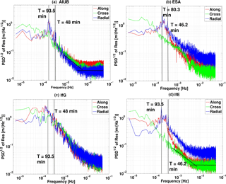
Figure 12Spectral analysis of Swarm C orbits from and (a) AIUB, (b) ESA,(c) IfG and (d) IfE in March 2016. Slope 0 represents white noise and slope −1 flicker noise.
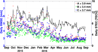
Figure 13Daily RMSEs of the ionosphere-free carrier phase residuals and the daily average STEC derived from Swarm C over all GPS satellites for 1 year of data from DoY 245, 2015 to DoY 244, 2016.
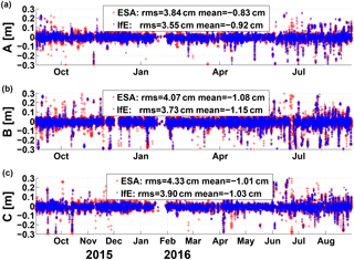
Figure 14SLR residuals over 1 year from DoY 245, 2015 to 244, 2016, for (a) Swarm A, (b) B and (c) C. The residuals for IfE are given in blue and ESA kinematic orbits in red.
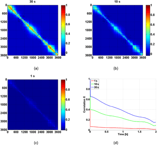
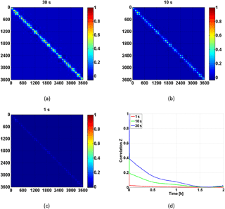
Figure 15Correlation matrix for 30 h time span in X-component obtained with a (a) 30 s, (b) 10 s and (c) 1 s data rate. The identical epochs (30 s interval) are extracted from the respective correlation matrix. Panel (d) shows the mean correlation over 2 h.
The computed kinematic orbits of Swarm C are also compared with the kinematic orbits from ESA (van den IJssel et al., 2015), IfG of TU Graz (Zehentner and Mayer-Gürr, 2015) and AIUB (Jäggi et al., 2016). Again, ESA reduced-dynamic orbits are the reference trajectory. The position residuals of all institutes from DoY 01 to DoY 07, 2016 are shown in Fig. 11. The rms values are given in the legend. Our results are in good agreement with the kinematic orbits derived from the other institutes.
In order to analyse the remaining deviations, a spectral analysis is performed for Swarm C for March 2016 in Fig. 12. The once-per-revolution periodic signatures in the along-track and radial direction are well identified in all orbits except that of IfG, with 93.5 min for IfE and AIUB, 80.3 min for ESA. Besides the once per revolution, a twice-per- revolution periodic signature can be observed in the three orbits probably due to the impact of ionospheric scintillations at polar areas, with 46.2 min for IfE and ESA, 48 min for AIUB. Interestingly, the signatures of the cross track are different; IfE orbits are showing no significant periodicity. A half-day periodicity can be observed in AIUB and ESA orbits. The remaining high-frequency noise in the radial component is clearly visible in IfE and ESA orbits, which is linked to the observation noise during the passage of ionosphere-active areas. For the along- and cross-track component, IfE is at the AIUB level for frequencies larger than 10−3 Hz. High-frequency white noise contribution dominates in IfE and AIUB orbits until 250 s and ESA and Graz orbits until 100 s. Then the flicker noise persists in all the components. Between once per revolution and twice per revolution, some along-track and radical components in IfE persist periodically. The cross-track component of IfE is showing a f−1 behaviour.
An additional possibility to assess the orbit quality is to analyse the residuals of GPS observations (van den IJssel et al., 2015). The daily RMSEs of the ionosphere-free carrier phase residuals for Swarm A, B and C for 1 year of data from DoY 245, 2015 to 244, 2016 are shown in Fig. 13, for example. The average of the daily RMSEs are at the 4 mm level. As expected, the daily RMSEs of Swarm B are slightly smaller than for Swarm A and C. Swarm A and C show similar results. The rms values show a decreasing trend with time, which could be related to the decreasing activity of ionosphere. Comparing Swarm A and C in September 2015, a significant improvement due to the update of the bandwidth on Swarm C can be observed.
The comparison with reduced-dynamic orbits and the residuals of GPS observations is an internal validation of the orbits. Independent satellite laser ranging (SLR) measurements provide another external validation of the orbits. The GPS-derived kinematic orbits are first interpolated with a polynomial of degree 5 to the observation time of SLR measurements. Then, the computed ranges between the ground stations of tracking networks and the GPS-derived kinematic orbits are compared with the observed laser ranges. The coordinates of the ground stations are given in ITRF2014 (Altamimi et al., 2016) with consideration to the solid Earth tide and ocean loading (FES2004 Lyard et al., 2006). The positions of the laser reflector in the satellite reference frame are given in Astrium GmbH (2013). The tropospheric delay and relativistic effects are also corrected. Reflector-dependent range corrections are not applied. The SLR residuals for Swarm A, B and C from DoY 245, 2015 to DoY 244, 2016 are shown in Fig. 14. The SLR residuals larger than 30 cm are excluded as outliers. The RMSEs of SLR residuals are at a 3–4 cm level for our orbits and ESA kinematic orbits.
3.3 Covariance Information
The least-squares estimation provides not only the coordinates but also the variance–covariance information, which is important for gravity field recovery (Jäggi et al., 2011). Usually, only the mathematical correlations between the coordinates at the same epoch are considered. But the carrier phase ambiguities also correlate coordinates over multiple epochs. The fully populated formal variance–covariance matrices for 30 h PPP are computed with 30, 10 and 1 s GPS observation data rates, respectively. For undifferenced 30 and 10 s GPS observations, the covariance matrix can be directly computed from the inverse of the normal equation. However, due to computational limitation, the covariance of 1 s is computed epoch-wise by the sequential inversion of block submatrices. For a better illustration of the covariance matrix, it is converted into a correlation matrix.
Figure 15 shows the corresponding correlation matrix of the Earth-fixed X-component for all 30 h in the 30 s intervals. The X-coordinates of 30 s rate are strongly correlated at the polar areas (red spots) and the correlation decreases with time (Fig. 15a). The temporal mathematical correlation between two successive 30 s epochs is around 0.6. The correlation time varies between 0.5 and 2.5 h and shows a 24 h variation, which is caused by the period of the GPS constellation. Due to the increased number of observations, the correlation for 10 s observations is much lower than for 30 s. The correlation between two successive epochs is only around 0.4. But it shows a pattern similar to 30 s observations (Fig. 15b). As expected, with increased observations frequency, the correlation for the 1 s data rate is further decreased with a correlation between two successive epochs lower than 0.1 (Fig. 15c). Thus, the increase of data implies an increasing number of coordinates that are less correlated with the ambiguities, since no filter model is used in our PPP approach. The average correlation of X-components with times for the different rates is shown in Fig. 15d. The X-components are still correlated for 30 s data rate after 2 h. For the 10 s data rate, the average correlation is around 0.4 after 10 s and decreases smoothly to 0.1 after 2 h. There is almost no mathematical correlation for 1 s data rate, and the correlation drops immediately to 0.05 after 1 s. The correlation structure of the Earth-fixed Y-component is similar to the X-component.
The correlation structures of the Z-component for 30, 10 and 1 s data rates are shown in Fig. 16. The correlation between two successive epochs is similar to the X-component, around 0.4, 0.2 and below 0.1 for 30, 10 and 1 s data rates, respectively. However, the correlation times are much shorter than for the X-component, shown in Fig. 16. After an hour, the correlations can be neglected for 30 and 10 s data rates.
In this contribution, we present the approach for the determination of the IfE Swarm kinematic orbit with PPP. Since the GPS data quality is a prerequisite for the high quality of kinematic orbit, a thorough analysis was first performed. Although only 8 channels are available, the requirements for an accurate positioning are fulfilled. If the reacquisition time can be shortened, the tracking performance can be further improved. Carrier phase observations at both frequencies are strongly disturbed by ionospheric scintillations, where noise larger than 0.2 m degrades the detection of cycle slips. The approach is proposed, which allows for a successful cycle-slip repairing of around 95 %. It is worth mentioning that almost all the cycle slips occur on L2 due to ionospheric scintillations.
Precise kinematic orbits at IfE are generated with the PPP method. The differences between our kinematic orbits and the ESA reduced-dynamic orbits are at 1.5, 1.5 and 2.5 cm level in along-track, cross-track and radial directions, respectively. The daily rms values of ionosphere-free carrier phase residuals are at 4 mm level, showing strong internal consistency. The spectral analysis of the orbits highlights the once-per-revolution period and higher harmonics as well as the dominant noise processes. A comparison with orbits from other institutes shows very good agreement with the rms level. A comparison with SLR underlines the accuracy of the kinematic orbits of 3–4 cm. Due to the ambiguities in the carrier phase, the coordinates are correlated. The mathematical temporal correlation between two successive epochs is larger than 0.6 for the 30 s data rate. The correlation decreases with increased sampling frequency. For a 1 s data rate, the correlation between two successive epochs is below 0.1.
The Swarm kinematic orbits from AIUB can be found at ftp://ftp.aiub.unibe.ch/LEO_ORBITS/SWARM/, last access: 17 September 2018.
The Swarm kinematic orbits from IfG TU Graz can be found at ftp://ftp.tugraz.at/outgoing/ITSG/tvgogo/orbits/Swarm/v2/, last access: 17 September 2018.
The Swarm kinematic orbits from ESA can be found at ftp://swarm-diss.eo.esa.int/Level2daily/Latest_baselines/POD/KIN/, last access: 17 September 2018.
Swarm Level 1b and Level 2 products can be found ftp://swarm-diss.eo.esa.int, last access: 17 September 2018.
The CODE orbits and clock products can be downloaded from: ftp://ftp.igs.org/pub/product/, last access: 17 September 2018.
The Swarm kinematic orbits from IfE Hannover are still under evaluation and will be accessible for the public soon.
LR developed the code, designed the experiments and prepared the manuscript. SS contributed to the interpretation of the results and correction of the manuscript.
The authors declare that they have no conflict of interest.
This article is part of the special issue “Dynamics and interaction of processes in the Earth and its space environment: the perspective from low Earth orbiting satellites and beyond”. It is not associated with a conference.
This project is part of the Consistent Ocean Mass Time Series from LEO Potential Field Missions (CONTIM) and funded by the Deutsche Forschungsgemeinschaft
(DFG) under the SPP1788 Dynamic Earth which is gratefully acknowledged. We
would like to thank ESA for providing Swarm data. The Swarm kinematic orbits
have been made available by ESA, AIUB and IfG, TU Graz. GPS orbits and clocks
have been obtained from the Center for Orbit Determination in Europe (CODE).
The SLR residuals are kindly provided by Anno Löcher of Institute of
Geodesy and Geoinformation, University of Bonn. TU Delft is also very
appreciated for providing the PCV maps. The support of all these institutions
is gratefully acknowledged.
The publication of
this article was funded by the open-access
fund of Leibniz
Universität Hannover.
The topical editor,
Monika Korte, thanks two anonymous referees for help in evaluating this
paper.
AIUB: The Swarm kinematic orbits, available at: ftp://ftp.aiub.unibe.ch/LEO_ORBITS/SWARM/, last access: 17 September 2018.
Altamimi, Z., Rebischung, P., Métivier, L., and Collilieux, X.: ITRF2014: A new release of the International Terrestrial Reference Frame modeling nonlinear station motions, J. Geophys. Res.-Sol. Ea., 121, 6109–6131, https://doi.org/10.1002/2016JB013098, 2016. a
Astrium GmbH: Swarm Instrument Positions in Spacecraft Coordinates, SW.TN.ASTR.SY.00012298, Issue 3, 2013. a
Blewitt, G.: An automatic Editing Algorithm for GPS data, Geophys. Res. Lett., 17, 199–202, 1993. a
Bock, H., Dach, R., Jäggi, A., and Beutler, G.: High-rate GPS clock corrections from CODE: support of 1 Hz applications, J. Geodesy, 83, 1083–1094, https://doi.org/10.1007/s00190-009-0326-1, 2009. a
Buchert, S., Zangerl, F., Sust, M., André, M., Eriksson, A., Wahlund, J., and Opgenoorth, H.: Swarm observations of equatorial electron densities and topside GPS track losses, Geophys. Res. Lett., 42, 2088–2092, https://doi.org/10.1002/2015GL063121, 2015. a
Cai, C., Liu, Z., Xia, P., and Dai, W.: Cycle slip detection and repair for undifferenced GPS observations under high ionospheric activity, GPS Solut., 17, 247–260, https://doi.org/10.1007/s10291-012-0275-7, 2013. a
Dach, R., Schaer, S., Arnold, D., Orliac, E., Prange, L., Sušnik, A., Villiger, A., and Jäggi, A.: CODE final product series for the IGS. Published by Astronomical Institute, University of Bern, https://doi.org/10.7892/boris.75876, 2016. a
Dahle, C., Arnold, D., and Jäggi, A.: Impact of tracking loop settings of the Swarm GPS receiver on gravity field recovery, Adv. Space Res., 59, 2843–2854, https://doi.org/10.1016/j.asr.2017.03.003, 2017. a, b
ESA: New GPSR settings on Swarm A and B satellites, available at: https://earth.esa.int/web/guest/missions/esa-operational-eo-missions/swarm/news/, last access: 29 October 2015. a
ESA: Swarm – Software issue in Rinex converter fixed, available at: https://earth.esa.int/web/guest/missions/esa-operational-eo-missions/swarm/news/, last access: 15 April 2016. a, b
ESA: The Swarm kinematic orbits, available at: ftp://swarm-diss.eo.esa.int/Level2daily/Latest_baselines/POD/KIN/, last access: 17 September 2018.
Estey, L. and Meertens, C.: TEQC: The Multi-Purpose Toolkit for GPS/GLONASS Data, GPS Solut., 3, 42–49, https://doi.org/10.1007/PL00012778, 1999. a
Friis-Christensen, E., Lühr, H., Knudsen, D., and Haagmans, R.: Swarm – an earth observation mission investigating geospace, Adv. Space Res., 41, 210–216, https://doi.org/10.1016/j.asr.2006.10.008, 2008. a
Hofmann-Wellenhof, B., Lichtenegger, H., and Wasle, E.: GNSS – Global Navigation Satellite Systems, Springer, Vienna, p. 203, https://doi.org/10.1007/978-3-211-73017-1, 2008. a
IfG TU Graz: The Swarm kinematic orbits, available at: ftp://ftp.tugraz.at/outgoing/ITSG/tvgogo/orbits/Swarm/v2/, last access: 17 September 2018.
IGS: The CODE orbits and clock products, available at: ftp://ftp.igs.org/pub/product/, last access: 17 September 2018.
IS-GPS-200H: Interface Specifications-Navstar GPS space segment/navigation user interfaces, available at: https://www.gps.gov/technical/icwg/IS-GPS-200H.pdf (last access: 17 September 2018), 2013. a
Jäggi, A., Prange, L., and Hugentobler, U.: Impact of covariance information of kinematic positions on orbit reconstruction and gravity field recovery, Adv. Space Res., 47, 1472–1479, https://doi.org/10.1016/j.asr.2010.12.009, 2011. a
Jäggi, A., Dahle, C., Arnold, D., Bock, H., Meyer, U., Beutler, G., and van den IJssel, J.: Swarm kinematic orbits and gravity fields from 18 months of GPS data, Adv. Space Res., 57, 218–233, https://doi.org/10.1016/j.asr.2015.10.035, 2016. a, b, c, d, e
Lyard, F., Lefevre, F., Letellier, T., and Francis, O.: Modelling the global ocean tides: modern insights from FES2004, Ocean Dynam., 56, 394–415. https://doi.org/10.1007/s10236-006-0086-x, 2006. a
Melbourne, W. G.: The case for ranging in GPS based geodetic systems, in: Proceedings of the 1st international symposium on precise positioning with the global positioning system, Rockville, ML, 373–386, 1985. a
Schmid, R., Steigenberger, P., Gendt, G., and Rotacher, M.: Generation of a consistent absolute phase center correction model for GPS receiver and satellite antennas, J. Geodesy, 81, 781–798, https://doi.org/10.1007/s00190-007-0148-y, 2007. a
Swarm TEC Product: ESA Swarm L2 TEC Product Description, Doc. no: SW-TR-GFZ-GS-0007, Rev: 4, 2017-05-22, 2017. a
Swarm: Swarm Level 1b and Level 2 products, available at: ftp://swarm-diss.eo.esa.int, last access: 17 September 2018.
Švehla, D. and Rothacher, M.: Kinematic and reduced-dynamic precise orbit determination of low earth orbiters, Adv. Geosci., 1, 47–56, https://doi.org/10.5194/adgeo-1-47-2003, 2003. a, b
van den IJssel, J., Encarnação, J., Doornbos, E., and Visser, P.: Precise science orbits for the Swarm satellite constellation, Adv. Space Res., 56, 1042–1055, https://doi.org/10.1016/j.asr.2015.06.002, 2015. a, b, c, d, e, f, g
van den IJssel, J., Forte, B., and Montenbruck, O.: Impact of Swarm GPS receiver updates on POD performance, Earth Planets Space, 68, 85, https://doi.org/10.1186/s40623-016-0459-4, 2016. a, b, c, d
Wu, J., Wu, S., Hajj, G., Bertiger, W., and Lichten, S.: Effects of antenna orientation on GPS carrier phase, Manuscripta Geodaetica, 18, 91–91, 1993. a
Wübbena, G.: Software developments for geodetic positioning with GPS using TI 4100 code and carrier measurements, in: Proceedings of the 1st international symposium on precise positioning with the global positioning system, Rockville, ML, 403–412, 1985. a
Xiong, C., Stolle, C., and Lühr, H.: The Swarm satellite loss of GPS signal and its relation to ionospheric plasma irregularities, Space Weather, 14, 563–577, https://doi.org/10.1002/2016SW001439, 2016. a
Zangerl, F., Griesauer, M., Sust, O., Montenbruck, S., Buchert, and Garcia, A.: SWARM GPS precise orbit determination receiver initial in-orbit performance evaluation, in: Proceedings of the 27th International Technical Meeting of the Satellite Division of the Institute of Navigation (ION GNSS+) Tampa, Florida, 1459–1468, 2014. a, b, c
Zehentner, N. and Mayer-Gürr, T.: Precise orbit determination based on raw GPS measurements, J. Geodesy, 90, 275–286, https://doi.org/10.1007/s00190-015-0872-7, 2015. a, b, c
Zumberge, J. F., Heflin, M. B., Jefferson, D. C., Watkins, M. M., and Webb F. H.: Precise point positioning for the efficient and robust analysis of GPS data from large networks, J. Geophys. Res., 102, 5005–5017, https://doi.org/10.1029/96JB03860, 1997. a


